Push-pull switching power converter

a technology of switching power converter and push-pull, which is applied in the direction of electric variable regulation, process and machine control, instruments, etc., can solve the problems of reducing power conversion efficiency, complex structure, and switching noise, and achieves simple and compact converter, high conversion efficiency, and reduced high-frequency switching noise

Inactive Publication Date: 2006-12-26
FLYING MOLE CORP
View PDF6 Cites 12 Cited by
  • Summary
  • Abstract
  • Description
  • Claims
  • Application Information

AI Technical Summary

Benefits of technology

[0008]The present invention has been accomplished in view of the above-mentioned problems, and it is an object of the present invention to provide a simple and compact push-pull switching power converter with low noise and a high power factor.
[0010]According to the present invention, the push-pull switching power converter has a switching voltage and switching current in the form of a sine wave. Thus, the high-frequency switching noise can be significantly reduced in principle. Also, by adapting a push-pull switching configuration, a simple and compact converter with high conversion efficiency, a high power factor, and a stable output can be achieved.

Problems solved by technology

In known switching power supply circuits, as described above, a dead-time control circuit and a zero-cross control circuit are essential, thus complicating the structure.
Furthermore, since the signal wave used for switching is a rectangular pulse wave, switching noise tends to occur.
Therefore, the power conversion efficiency is decreased, which is a problem.

Method used


Image

  • Push-pull switching power converter
  • Push-pull switching power converter
  • Push-pull switching power converter

Examples


first embodiment

A. First Embodiment

[0015]A push-pull switching power converter according to a first embodiment of the present invention will be described below. According to the first embodiment, the push-pull switching power converter inputs a direct electric current and outputs a direct electric current; that is, the push-pull switching power converter is a DC-to-DC converter which converts a DC voltage to another DC voltage.

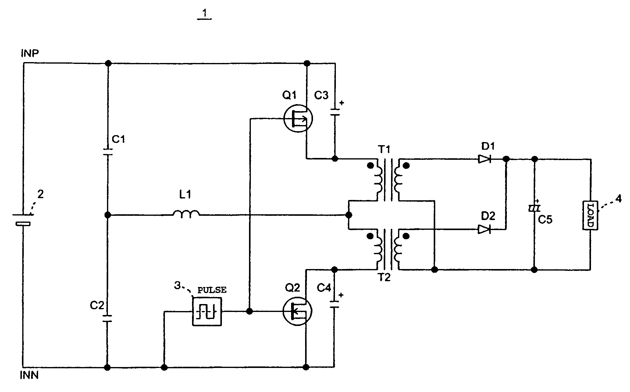
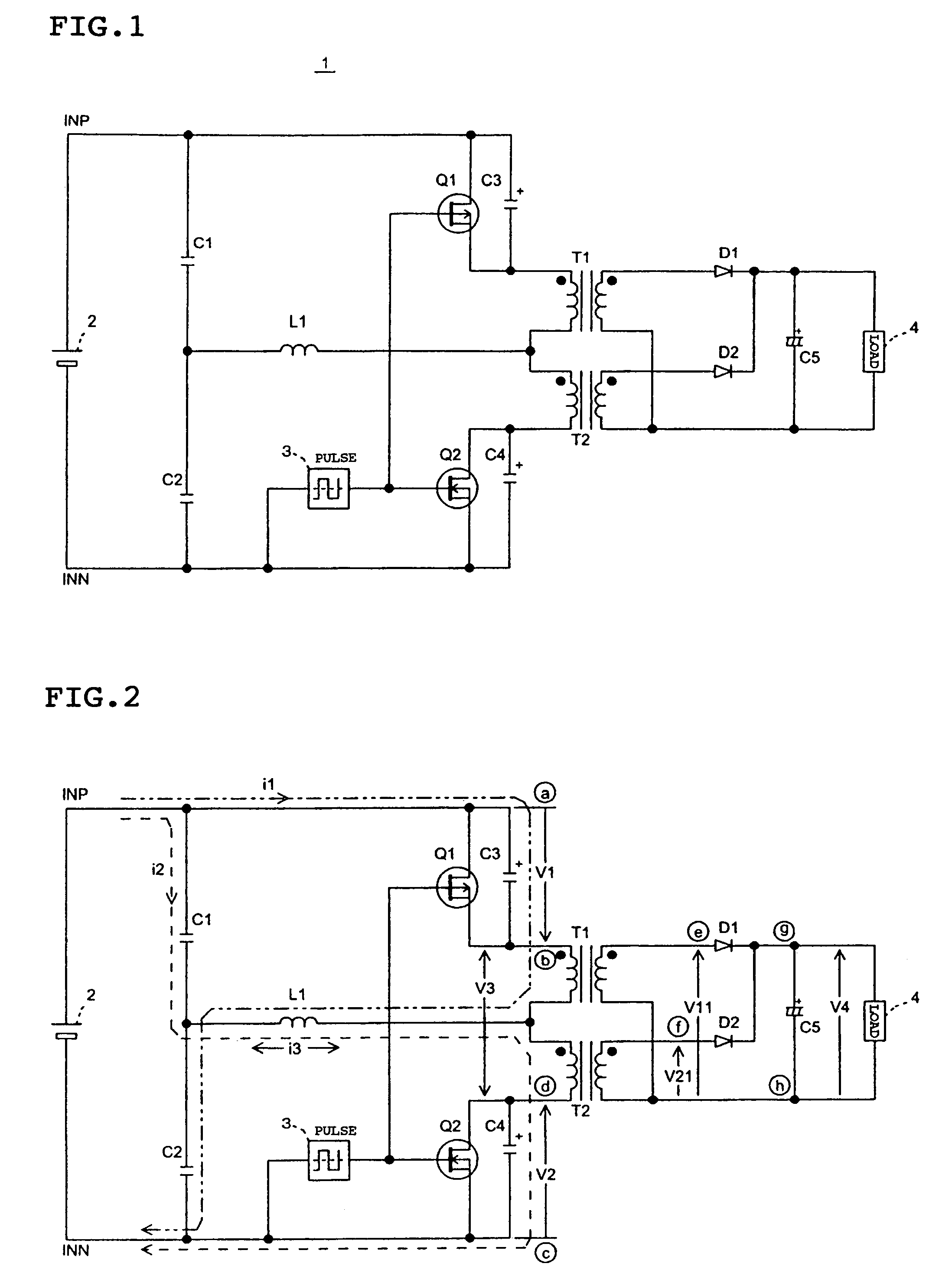
[0016]FIG. 1 is an overall circuit diagram of the push-pull switching power converter according to the first embodiment. As shown in FIG. 1, a power converter (DC-to-DC converter) 1 according to the first embodiment includes a DC input source 2, a pulse generator 3, a load 4, switching devices Q1 and Q2, capacitors C1 to C5, transformers T1 and T2, and diodes D1 and D2.

[0017]The DC input source 2 may be a dry battery or a storage battery. Additionally, the DC input source 2 may be a component for converting a commercial power source to a DC power source. In the latter case, t...

second embodiment

B. Second Embodiment

[0043]A push-pull switching power converter according to a second embodiment of the present invention will be briefly described next with reference to FIG. 4 while focusing on the differences from the first embodiment.

[0044]A first difference is that, in the second embodiment, coils L2 and L3 respectively connected to the primary windings of transformers T1 and T2 in series are used for current resonance while the coil L1 provided in the path common to the first and second electric currents is used for current resonance in the first embodiment.

[0045]A second difference is that, in the second embodiment, a switching device Q1 at the high potential side is composed of an NMOS transistor, as with a switching device Q2 at low potential side. This allows switching devices Q1 and Q2 having the same characteristic to be easily obtained.

[0046]A third difference is that, in the second embodiment, since an NMOS transistor is used as the switching device Q1, an output of th...


PUM


Abstract

A push-pull switching power converter includes, between high and low output terminals of a DC power source, a series circuit having a first switching device, a primary winding of a first transformer, a primary winding of a second transformer, and a second switching device in this order, and a series circuit composed of two capacitors, as well as a partial path for current resonance. The partial path connects middle points of the two series circuits. Voltage resonance causes the waveform of a switching voltage, which corresponds to the difference in voltages between high potential terminal of a primary of the first transformer and low potential terminal of a primary of the second transformer, to be a sine wave. Current resonance causes the waveform of a switching current, which corresponds to a combined current of primary winding currents of the first transformer and the second transformer, to be a sine wave.

Description

CROSS-REFERENCE TO RELATED APPLICATION[0001]This application claims, under 35 USC 119, priority of Japanese Application No. 2004-225330 filed Aug. 2, 2004.BACKGROUND OF THE INVENTION[0002]1. Field of the Invention[0003]The present invention relates to a push-pull switching power converter and, in particular, to a power converter, such as an AC-to-DC converter and a DC-to-DC converter, using a pair of switching devices.[0004]2. Description of the Related Art[0005]Switching power supply circuits having a pair of switching devices and carrying out desired power conversion by switching on and off the switching devices control on and off of each switching device using a rectangular wave pulse (refer to, for example, Japanese Patent Application Laid-Open No. 4-364362).[0006]Such switching power supply circuits also carry out dead-time control to prevent a through current flowing between the pair of switching devices and carry out timing control (zero cross control) to determine a timing f...

Claims


Application Information

Patent Timeline
Patent Type & Authority Patents(United States)
IPC IPC(8): H02M3/335
CPCH02M3/3372
Inventor YAMADA, YASUOOGAWA, HIROSHI
Owner FLYING MOLE CORP
Why Eureka
Try Eureka