Mapping between virtual local area networks and fibre channel zones

a technology of fibre channel zone and virtual local area network, applied in the field of data transfer, can solve the problem that the stations not belonging to the same vlan cannot directly transfer data between themselves

Inactive Publication Date: 2006-12-26
CALLAHAN CELLULAR L L C
View PDF9 Cites 54 Cited by
  • Summary
  • Abstract
  • Description
  • Claims
  • Application Information

AI Technical Summary

Benefits of technology

[0008]It is an object of some aspects of the present invention to provide an improved method and apparatus for transferring data between locally grouped stations of networks operating under different protocols.
[0010]A “combination” grouping is formed by associating a specific VLAN with a specific zone, and data transfers between the VLAN and the zone of the combination grouping via the coupling gateway. The association is stored in the gateway. From the point of view of a VLAN station in the combination, all stations in the combination appear as native VLAN stations. From the point of view of an FC station within the combination, all stations appear as native FC zone stations. The gateway may store a multiplicity of associations, i.e., combination groupings, each combination grouping comprising a one-to-one mapping between a specific VLAN and a specific zone. Stations in the Ethernet network and in the FC network, within a specific combination grouping, may transfer data between themselves via the gateway. Allocating stations in networks operating under Ethernet and FC protocols to be part of one or more combination groupings increases flexibility of station grouping and simplifies security deployment in the infrastructure of the networks.

Problems solved by technology

However, stations which do not belong to the same VLAN cannot directly transfer data between themselves.

Method used


Image

  • Mapping between virtual local area networks and fibre channel zones
  • Mapping between virtual local area networks and fibre channel zones
  • Mapping between virtual local area networks and fibre channel zones

Examples


Embodiment Construction

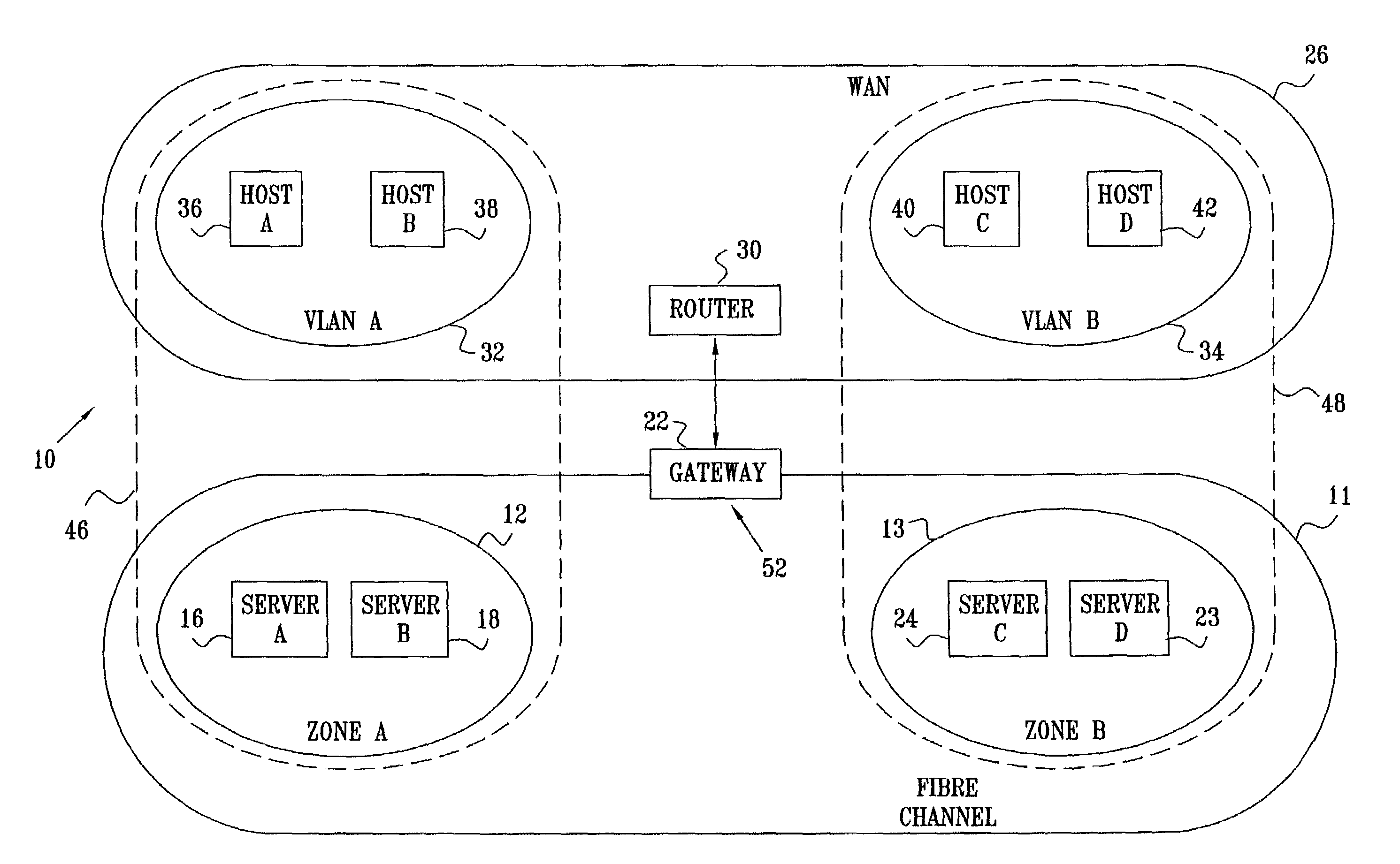
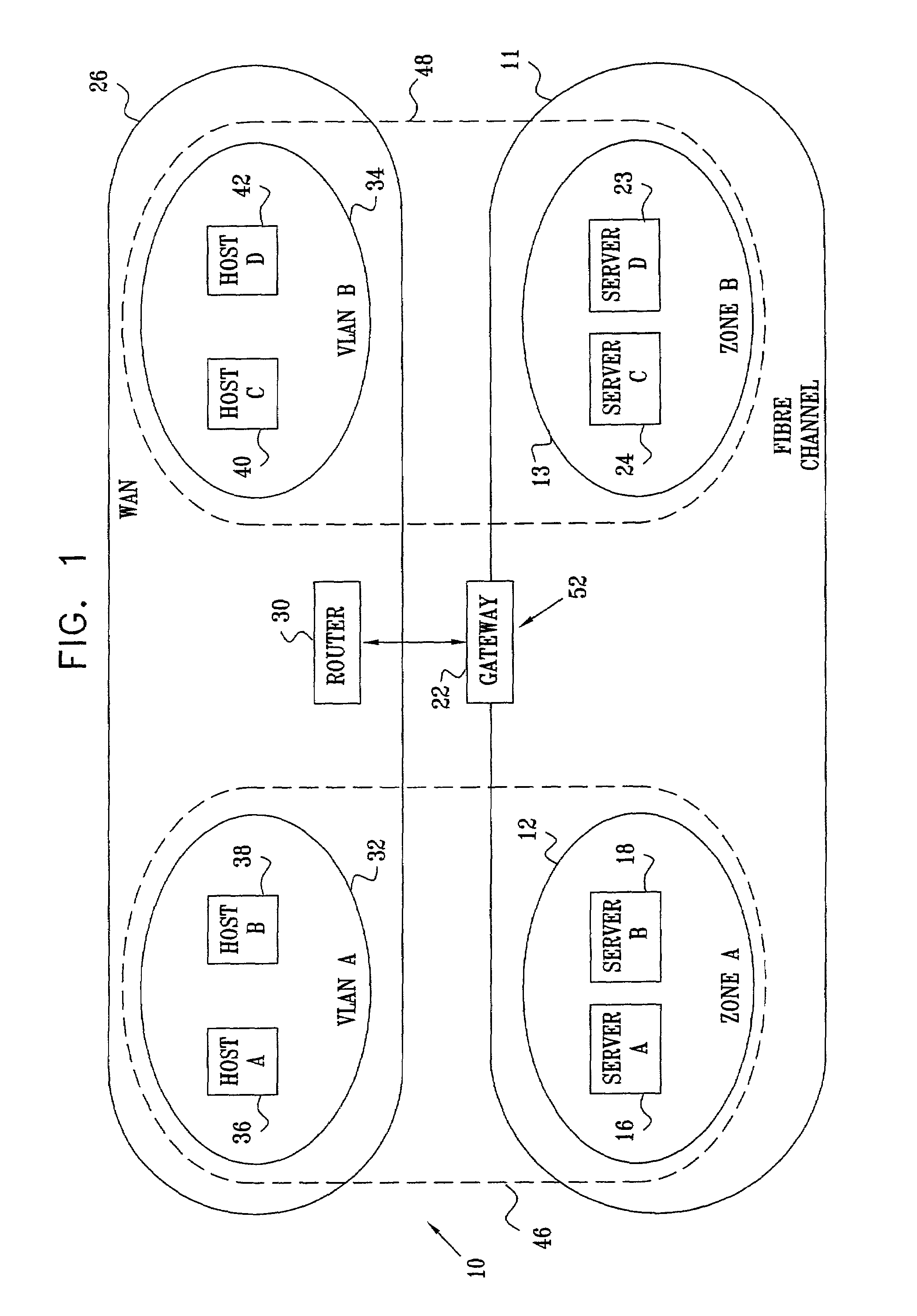
[0055]Reference is now made to FIG. 1, which is a schematic diagram of a compound network 10 coupling a Fibre Channel (FC) fabric 11 and an Ethernet Wide Area Network (WAN) 26, according to a preferred embodiment of the present invention. FC fabric 11 operates according to the FC-PH Fibre Channel protocol, and WAN 26 operates according to the IEEE 802.3(Z) Ethernet protocol, as described in the Background of the Invention. WAN 26 comprises generally similar Ethernet stations 36, 38, 40, and 42, herein assumed to be hosts, also respectively termed herein hosts A, B, C, and D. Within WAN 26 a first virtual local area network (VLAN) 32 comprises hosts 36 and 38 and a second VLAN 34 comprises hosts 40 and 42. VLANs 32 and 34 comprise subsets of stations within WAN 26, and are also herein referred to respectively as VLAN A and VLAN B. WAN 26 also comprises a router 30, which operates within WAN 26 so as, inter alia, to transfer data-frames generated within the WAN between stations of the...


PUM


Abstract

A method for transferring information between a first network comprising first-network-stations operating under an Ethernet protocol and a second network comprising second-network-stations operating under a Fibre Channel (FC) protocol, including grouping the first-network-stations into virtual local area networks (VLANs) which each transfer a respective VLAN-data-frame within the VLAN, and grouping the second-network-stations into FC zones which each transfer a respective zone-data-frame within the zone. The method further includes coupling the networks together using a gateway to convey data between the networks, configuring the gateway with an association mapping a primary VLAN and a primary zone, and translating in the gateway between a primary VLAN-data-frame and a primary zone-data-frame, responsive to the association, so as to convey primary-data between the primary VLAN and the primary zone via the gateway.

Description

FIELD OF THE INVENTION[0001]The present invention relates generally to data transfer, and specifically to data transfer between regions of networks operating under differing protocols.BACKGROUND OF THE INVENTION[0002]Methods for transferring data within networks, such as local area networks (LANs), metropolitan area networks (MANs), and storage area networks (SANs), rely on standard protocols describing how the data is transferred. Typically the data for a specific network is transferred as data-frames having a format defined by the protocol governing the functioning of the network. Two protocols which are used for transferring data at gigabit / s (Gbps) rates are an IEEE 802.3(Z) Ethernet protocol, issued by the Institute of Electrical and Electronics Engineers, Inc., New Jersey, and an FC-PH Fibre Channel protocol, issued by the American National Standards Institute, Washington, D.C. The Ethernet protocol transfers data-frames over a common bus by ensuring that no data collision occ...

Claims


Application Information

Patent Timeline
Patent Type & Authority Patents(United States)
IPC IPC(8): G06F15/16H04L12/46H04L29/08
CPCH04L12/4641H04L67/1097H04L69/329
Inventor CZEIGER, MOSHEFLINT, YOAVALEXANDROVICH, ILYAGISSIN, VICTORLIEBMAN, MARK
Owner CALLAHAN CELLULAR L L C
Why Eureka
Try Eureka