C-axis driving device of a computer numerical controlled lathing and milling machine

a technology of a driving device and a computer, which is applied in the direction of auxilary equipment, manufacturing tools, and manufacturing tools, can solve the problems of inability to move to a desired position, cannot mill a profile of a work piece very precisely, and the structure is too complicated, etc., to achieve the effect of simple structure, high speed and large torque outpu

Inactive Publication Date: 2007-01-02
LEADJECK AUTOMATION
View PDF9 Cites 6 Cited by
  • Summary
  • Abstract
  • Description
  • Claims
  • Application Information

AI Technical Summary

Benefits of technology

[0007]The primary object of the present invention is to provide a C-axis driving device of a computer numerical controlled lathing and milling machine. It has a simple structure to ach...

Problems solved by technology

The first disadvantage is that its structure is too complicated.
In addition, because its switch action is based on direct contact with a gear (or worm), a back-lash problem occurs.
Therefore, due to such back-lash, when a user control this CNC machine to drive the C-axis system, it cannot move to a desired position nor mill a profile of a work piece very precisely.
So, such conventional device is not commonly-used now.
But, such servo...

Method used


Image

  • C-axis driving device of a computer numerical controlled lathing and milling machine
  • C-axis driving device of a computer numerical controlled lathing and milling machine
  • C-axis driving device of a computer numerical controlled lathing and milling machine

Examples


Embodiment Construction

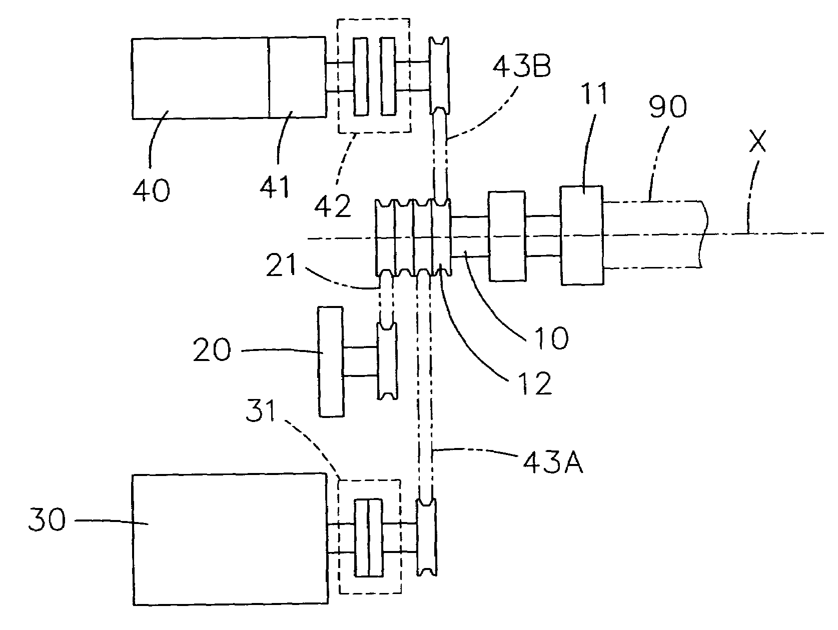
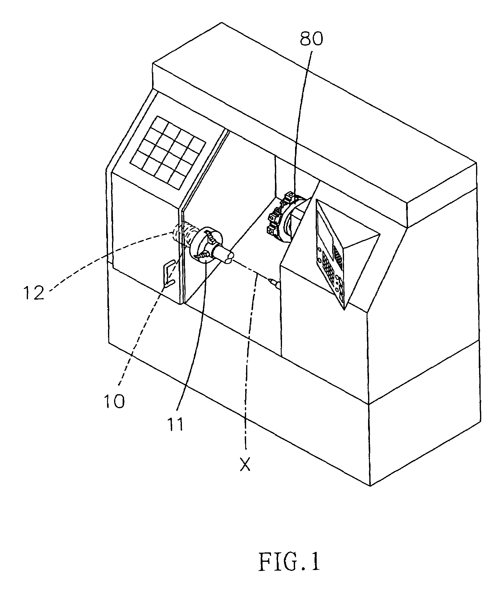
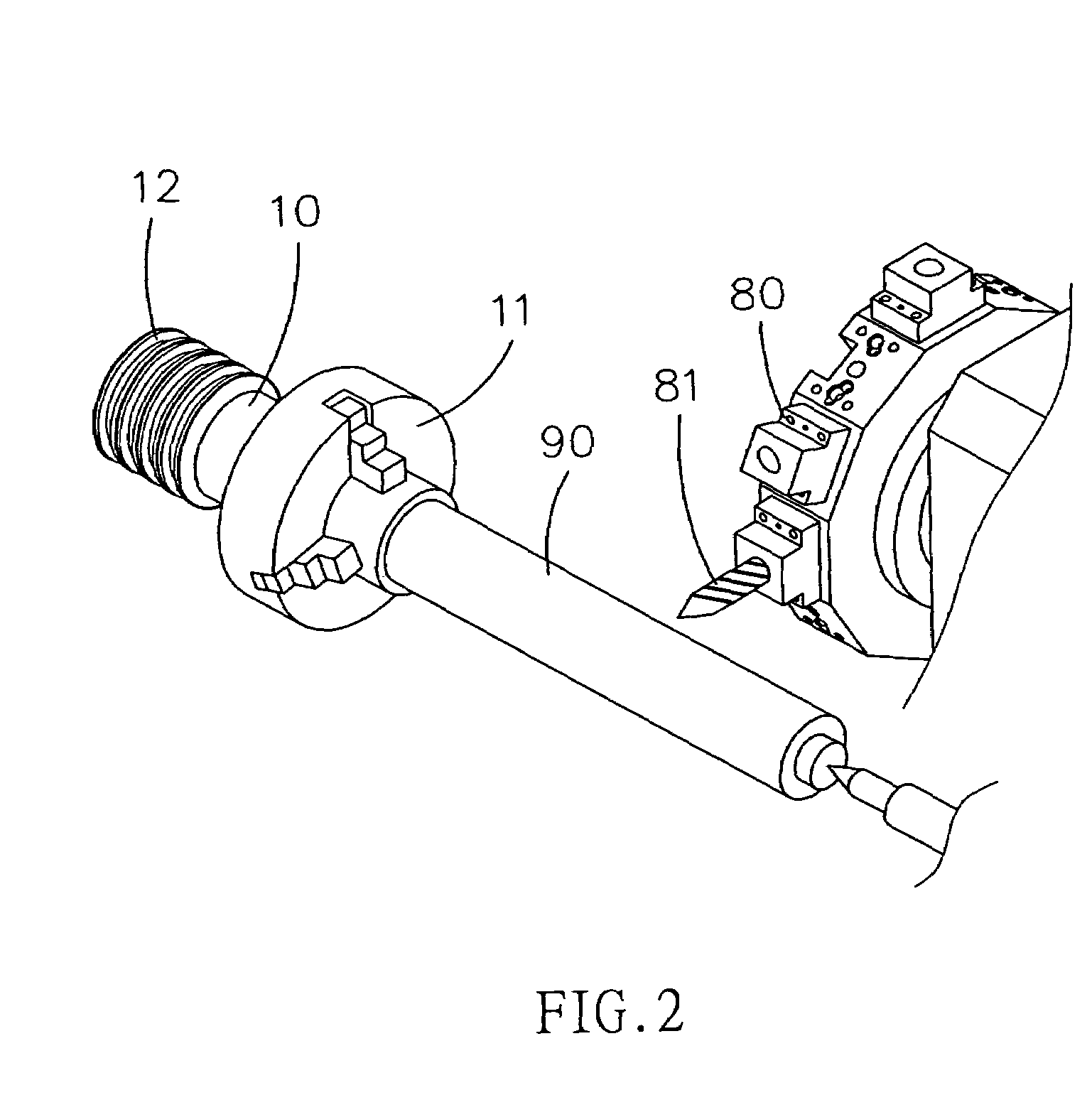
[0022]Referring to FIGS. 1, 2, 3A and 3B, the present invention is a C-axis driving device of a computer numerical controlled (briefly called CNC) lathing and milling machine. It mainly comprises a spindle 10, an encoder 20, a spindle motor 30, and a servo motor 40.

[0023]About this spindle 10, it has a clamping device 11 (for clamping a work piece 90) and a transmission portion 12. When this transmission portion 12 is driven and rotated, the spindle 10 and the clamped work piece 90 (shown by the phantom line) will rotate along a central axis X.

[0024]Concerning this encoder 20, it connects with the transmission portion 12 via an auxiliary timing belt 21. It can precisely detect the actual position or angle of the spindle 10 and the clamped work piece 90 and then send out the data to a controller of this CNC machine.

[0025]With regard to the spindle motor 30, it includes a first clutch 31. This first clutch 31 connects with a driving timing belt 43A first. Also, this driving belt 43A c...


PUM

PropertyMeasurementUnit
Timeaaaaaaaaaa
Speedaaaaaaaaaa

Abstract

A C-axis driving device of a computer numerical controlled (CNC) lathing and milling machine includes a spindle, an encoder, a spindle motor, and a servo motor. The spindle has a clamping device and a transmission portion. This encoder connects with the transmission portion via an auxiliary timing belt. The spindle motor and the servo motor connect with the transmission portion via at least one driving timing belt. Only at most one of the spindle motor and the servo motor is to drive this transmission portion at any time during operation. So, it has a simple structure to achieve the clutching change function. It can save more space. And, it can significantly reduce the manufacturing cost.

Description

BACKGROUND OF INVENTION[0001]1. Field of the Invention[0002]The present invention relates to a C-axis driving device of a computer numerical controlled (or briefly called CNC) lathing and milling machine. Particularly, by easily switching the spindle motor and the servo motor as started (there are torque output) or released (no torque output), it can achieve both the lathing work and the milling work on this CNC machine.[0003]2. Description of the Prior Art[0004]One of the traditional C-axis driving device of a computer numerical controlled (or briefly called CNC) lathing and milling machines can be seen in FIG. 7. With regard to the C-axis driving device, a conventional servo motor 71 is disposed above a spindle of a housing. Also, a double-lead worm 72 driven by the conventional servo motor 71 is disposed on this housing. All the description about other related elements is omitted here. The first disadvantage is that its structure is too complicated. In addition, because its switc...

Claims


Application Information

Patent Timeline
IPC IPC(8): B23P23/00B23C1/14
CPCB23P23/02B23Q16/025Y10T82/2593Y10T409/305656Y10T82/26Y10T82/2581Y10T409/308792Y10T29/5114
Inventor CHANG, WEN-YU
Owner LEADJECK AUTOMATION
Why Eureka
Try Eureka