
Phased activated sludge system

a phased activated sludge and wastewater technology, applied in biological water/sewage treatment, multi-stage water/sewage treatment, sustainable biological treatment, etc., can solve the problems of imposing energy costs on the treatment process, inefficient use of energy, and inability of wastewater treatment plant operators to control the balance between various beneficial forms of nitrogen in the activated sludge reactor vessel, etc., to achieve the effect of reducing power costs and simplifying piping and equipment layouts

Active Publication Date: 2007-01-02
AQUA AEROBIC SYST
View PDF15 Cites 16 Cited by
  • Summary
  • Abstract
  • Description
  • Claims
  • Application Information

AI Technical Summary

Benefits of technology

This approach reduces energy costs, simplifies equipment layouts, and enhances nutrient removal efficiency by allowing for anoxic conditions and targeted nutrient management, mimicking batch treatment processes within a continuous flow system.

Problems solved by technology

One of the disadvantages of using the same equipment for both the aeration and the mixing functions is that energy, a significant cost component of wastewater treatment, is not efficiently used.
Another disadvantage of a dual use or function aeration and mixing system is that the wastewater treatment plant operator is unable to control the balance between various beneficial forms of nitrogen in the activated sludge reactor vessel.
The RAS is reaerated in the reactor vessel, again imposing energy costs on the treatment process.
Moreover, by reaerating the RAS, a source of bacterial solids that provide a food source for organisms that preferentially expel phosphorus is wasted.
Such downstream removal processes require the expense of separate equipment, energy and chemical conditioning.

Method used


Image

  • Phased activated sludge system
  • Phased activated sludge system
  • Phased activated sludge system

Examples


Embodiment Construction

[0033]Set forth below is a description of what are currently believed to be the preferred embodiments or best examples of the inventions claimed. Future and present alternatives and modifications to these preferred embodiments are contemplated. Any alternatives or modifications which make insubstantial changes in function, in purpose, in structure or in result are intended to be covered by the claims of this patent.

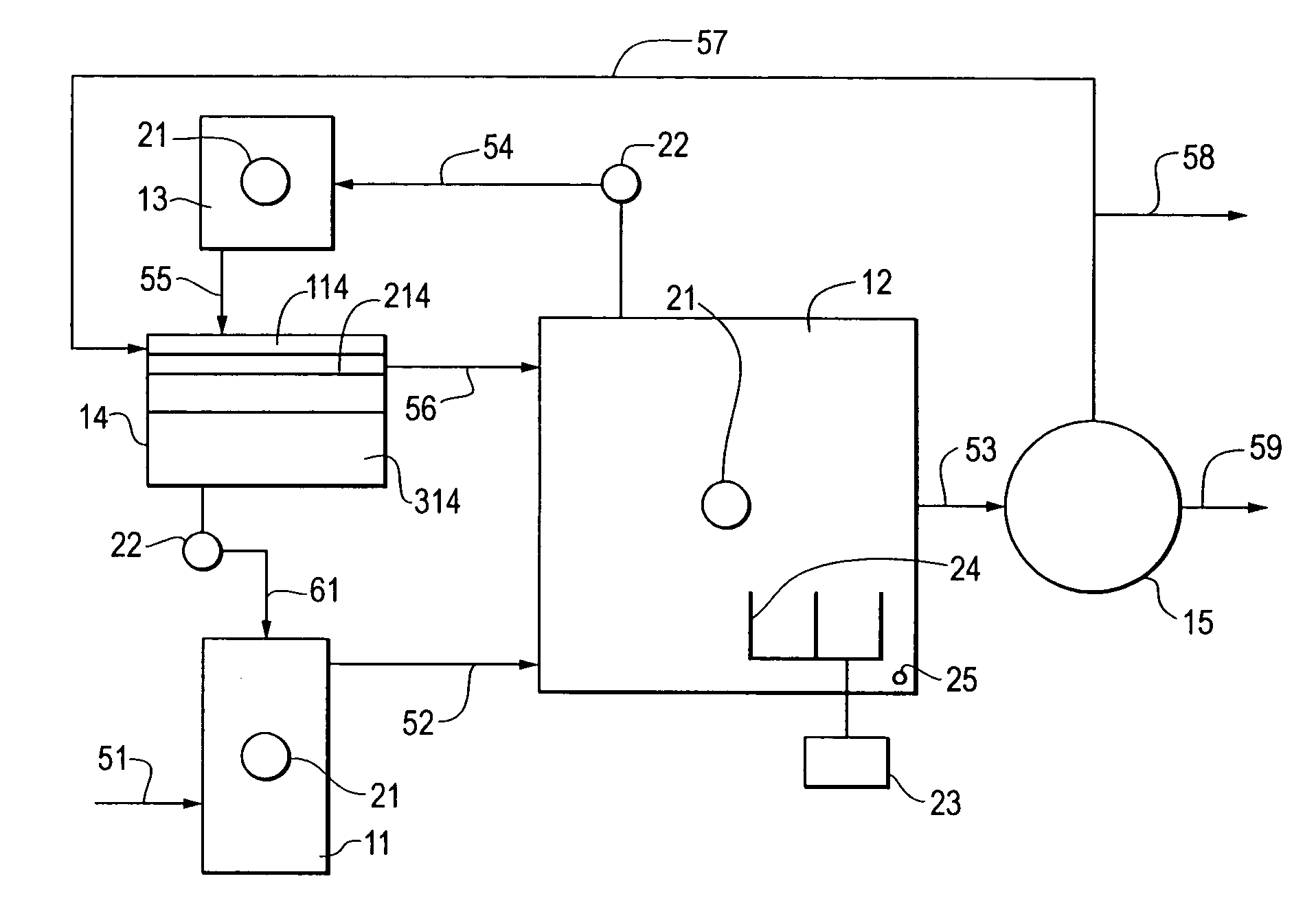
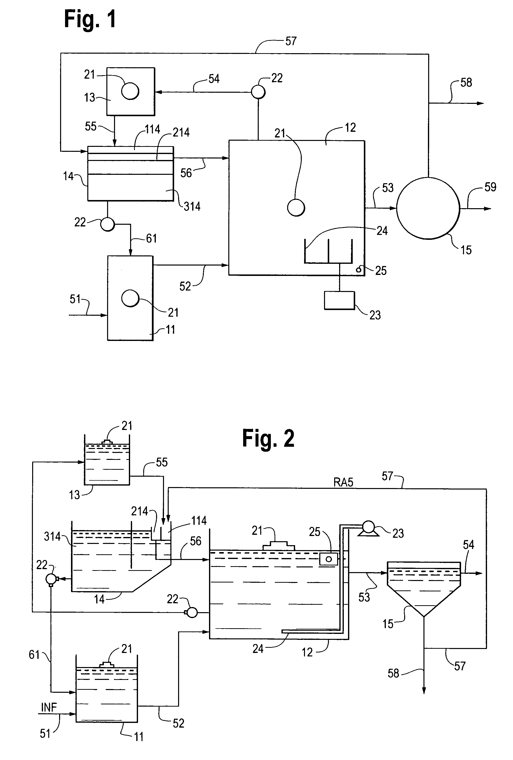
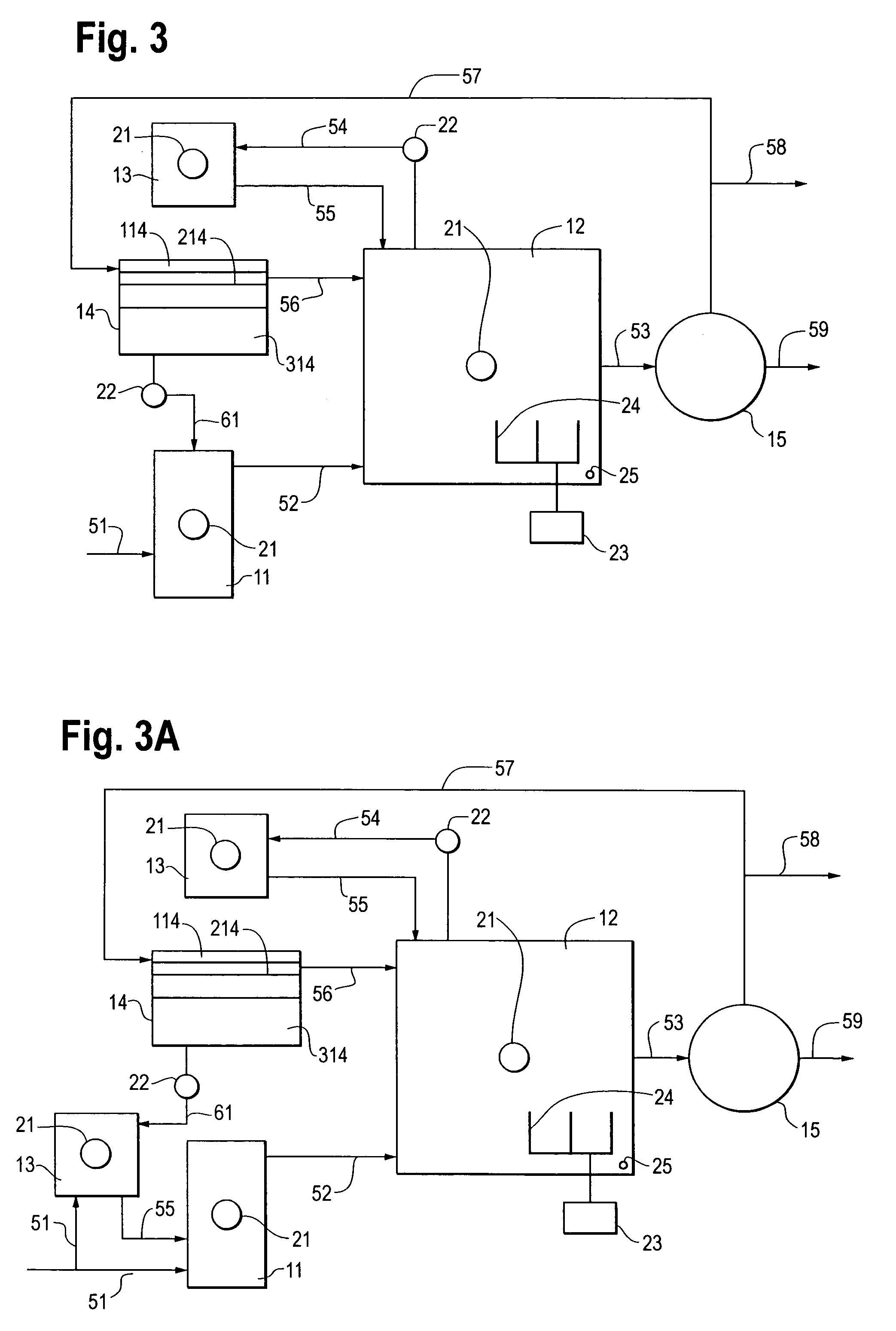
[0034]In one preferred embodiment of the invention (see FIGS. 1 & 2), influent is directed into an anaerobic vessel 11. The influent can be a raw wastewater influent, but is more commonly the effluent from a previous treatment step such as screening, chemical conditioning or other primary treatment processes as are known in the art. The influent channel 51 conveys the wastewater into an anaerobic vessel 11. It will be understood that a single anaerobic vessel 11 (see FIGS. 1–7), or a plurality of anaerobic vessels (not shown), may be used as part of the present inventions...


PUM

PropertyMeasurementUnit
concentrationaaaaaaaaaa

Abstract

The inventions describe a phased activated sludge treatment system that incorporates elements of batch treatment technology into a flow-through treatment process. Control of mixing and aeration systems are independent to facilitate the operation of the main reactor vessel in alternating aerated and anoxic conditions. Conditioning vessels in communication with the main reactor are employed to preferentially control the distribution and balance of nitrogen and phosphorus compounds in the reactor and to remove such biological nutrients concurrently with BOD and TSS in the wastewater. The inventions provide the beneficial results of providing greater operator control of flow-through treatment processes, power saving and reduced operation and maintenance costs in comparison to conventional flow-through treatment technologies.

Description

FIELD OF THE INVENTION[0001]The present inventions apply generally to the treatment of municipal and industrial wastewater using activated sludge processes. More specifically, the inventions are directed to activated sludge treatment processes carried out within flow-through wastewater treatment systems using time based process controls for aeration, nitrification, denitrification, phosphorus removal and related biosolids conditioning.BACKGROUND OF THE INVENTION[0002]Typical municipal and industrial wastewater contains pollutants expressed as biochemical oxygen demand (BOD). In a conventional flow-through wastewater treatment system which employs an activated sludge process for pollutant removal, the reactor vessel containing the activated sludge is continuously aerated as the wastewater passes through the vessel. Continuous aeration serves two purposes, it delivers oxygen to the active biomass of the activated sludge to sustain its ability to remove biochemical pollutants and it cr...

Claims


Application Information

Patent Timeline
Patent Type & Authority Patents(United States)
IPC IPC(8): C02F3/30
CPCC02F3/006C02F3/30C02F3/301C02F3/308Y10S210/906C02F2209/16C02F2209/18C02F2209/44Y10S210/903C02F2209/04Y02W10/10
Inventor REID, TERENCE K.
Owner AQUA AEROBIC SYST
Learn More