Combustion process for synthesis of carbon nanomaterials from liquid hydrocarbon

a technology of liquid hydrocarbon and combustion process, which is applied in the direction of combustion type, lighting and heating apparatus, capillary burner, etc., can solve the problems of high synthesis cost, unstable flame front, and backward movement of flame front towards the burner surface, so as to prolong the residence time of reacting materials, improve the yield of carbon nanomaterials, and retain heat from the burner

Active Publication Date: 2007-01-02
FRONTIER CARBON CORP
View PDF34 Cites 21 Cited by
  • Summary
  • Abstract
  • Description
  • Claims
  • Application Information

AI Technical Summary

Benefits of technology

[0032]In a preferred embodiment, a portion of the combustion apparatus downstream of the burner is insulated to better retain heat from the burner and to thereby maintain temperatures in the zone at levels that promote continued reaction to generate carbon nanomaterials. This insulated portion of the apparatus forms the reaction zone. Insulation of a portion of the combustion apparatus downstream of the burner functions to elongate the reaction zone, and thereby to extend the residence time of reacting materials at higher temperatures, enhancing the yield of carbon nanomaterials.
[0033]In another embodiment, additional oxidizer is supplied into the combustion apparatus along the w

Problems solved by technology

While the art recognizes significant potential for commercial application of carbon nanomaterials, and particularly for fullerenes, SWNTs and MWNTs, the high costs of synthesis of and the difficulties in obtaining these materials in the large amounts necessary for developing these applications has been a major impediment to practical application of these materials.
As the gas velocity through the burner is increased, the flame front tends to move away from the burner surface which can result in flame instability (i.e., the flame can be extinguished).
Cooling of the burner plate promotes heat loss from the burner surface causing the flame front to move back towards the burner surface.
However, cooling of the burner surface promotes deposit formation on that surface which can result in irregularities

Method used


Image

  • Combustion process for synthesis of carbon nanomaterials from liquid hydrocarbon
  • Combustion process for synthesis of carbon nanomaterials from liquid hydrocarbon
  • Combustion process for synthesis of carbon nanomaterials from liquid hydrocarbon

Examples


Embodiment Construction

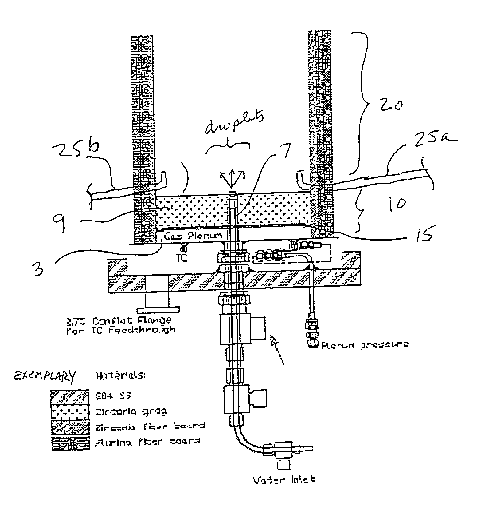
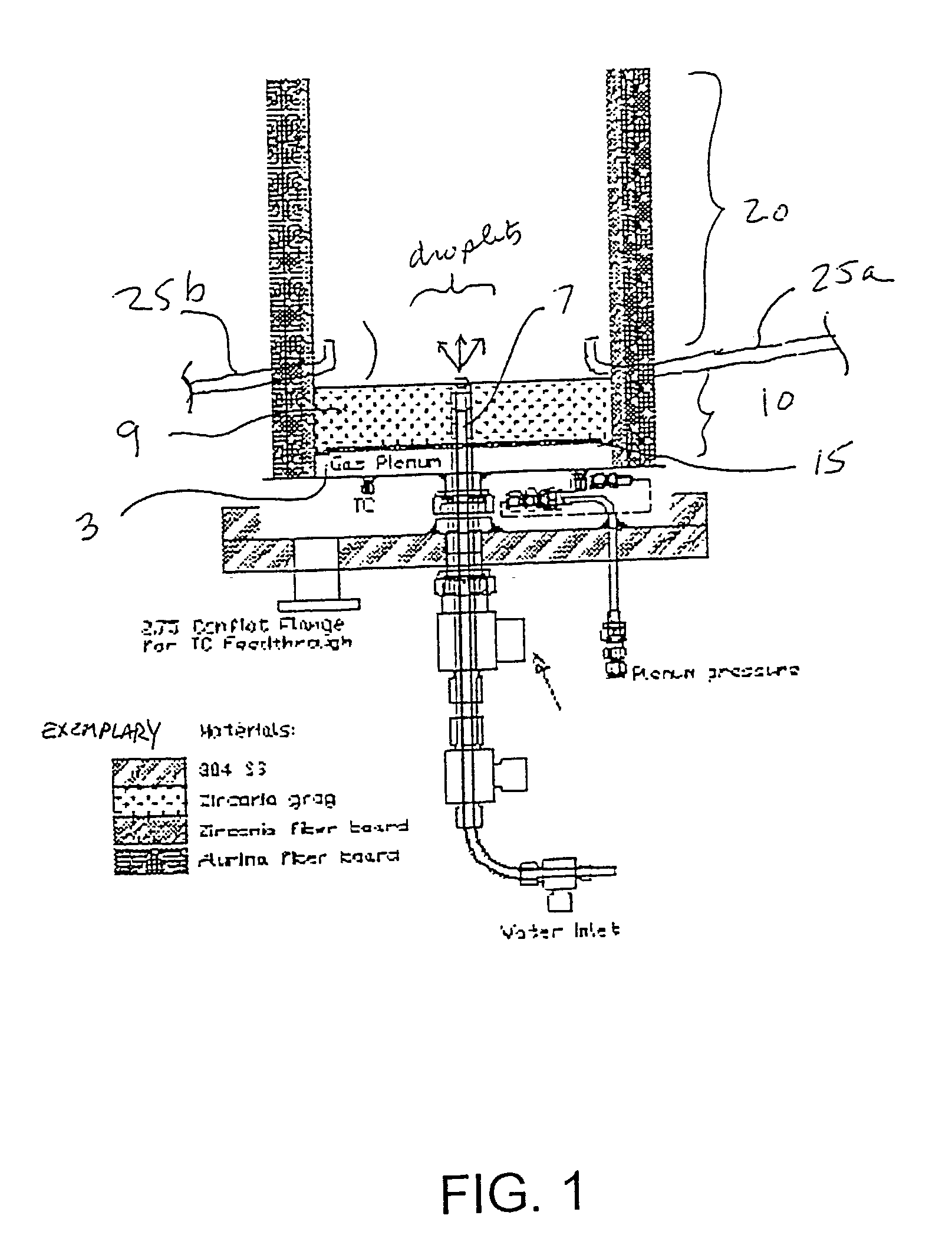
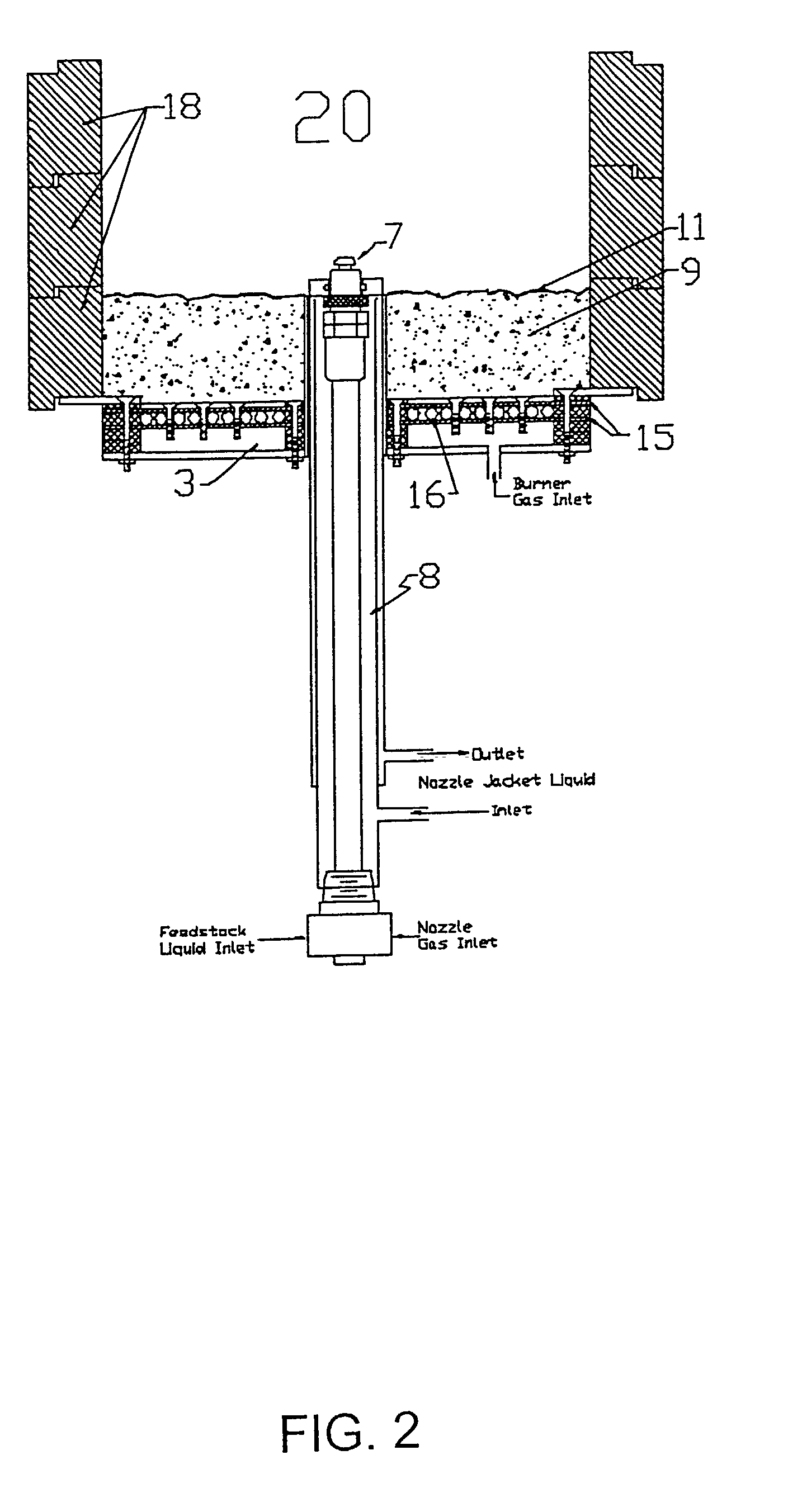
[0040]In the combustion system of this invention, flame stability conditions can be decoupled from the process of formation of carbon nanomaterials by first establishing a flame that may or may not operate fuel-rich, and then adding additional hydrocarbon. A wider variety of fuels, including those with low vapor pressures, can be used by introducing the hydrocarbon feedstock as a liquid into the flame. The hydrocarbon feedstock introduced breaks up into droplets, which evaporate and can at least partially burn. The addition of suitable spray injectors or other types of inlets or nozzles for introduction of feedstock droplets can be used with many types of burners. The liquid droplets may be introduced into the flame by any suitable apparatus, including nozzles, ultrasonic dispersers, and piezoelectric devices. The nozzle is most preferred, and may be vaned, impingement-type, air-atomizing, or electrostatic

[0041]There are two exemplary geometries for droplet introduction: axial and r...


PUM


Abstract

The present invention provides a combustion apparatus for the production of carbon nanomaterials including fullerenes and fullerenic soot. Most generally the combustion apparatus comprises one or more inlets for introducing an oxygen-containing gas and a hydrocarbon fuel gas in the combustion system such that a flame can be established from the mixed gases, a droplet delivery apparatus for introducing droplets of a liquid hydrocarbon feedstock into the flame, and a collector apparatus for collecting condensable products containing carbon nanomaterials that are generated in the combustion system. The combustion system optionally has a reaction zone downstream of the flame. If this reaction zone is present the hydrocarbon feedstock can be introduced into the flame, the reaction zone or both.

Description

CROSS-REFERENCE TO RELATED APPLICATIONS[0001]This application takes priority under 35 U.S.C. 119(e) from U.S. provisional application No. 60 / 337,750, filed Dec. 5, 2001.STATEMENT REGARDING FEDERALLY SPONSORED RESEARCH OR DEVELOPMENT[0002]This invention was made with government support from the U.S. Department of Energy under SBIR grant number DE-FG03-98ER82692. The United States government has certain rights in this invention.BACKGROUND OF THE INVENTION[0003]The invention relates to the production of carbon nanomaterials including fullerenes in sooting flames, and in particular to burners, combustion apparatus, and methods for carbon nanomaterial production. More specifically the invention relates to combustion apparatus and method of combustion for production of carbon nanomaterials in which a liquid hydrocarbon feedstock is introduced into a flame in the form of droplets, e.g., by spraying.[0004]The term “carbon nanomaterials” is used generally herein to refer to any substantially...

Claims


Application Information

Patent Timeline
IPC IPC(8): B01J19/26C01B31/02F23D14/16F23D99/00
CPCB82Y30/00B82Y40/00C01B31/0213C01B31/0233B01J19/26Y10S977/842B01J2219/00094B01J2219/00119B01J2219/00157F23D2900/21007C01B32/162C01B32/156C01B32/154
Inventor DIENER, MICHAEL D.ALFORD, J. MICHAELNABITY, JAMESHITCH, BRADLEY D.
Owner FRONTIER CARBON CORP
Why Eureka
Try Eureka