Electrophotographic photosensitive member

a photosensitive member and electrophotography technology, applied in the direction of electrographic process apparatus, optics, instruments, etc., can solve the problems of low resistivity, image deletion phenomenon, and inability to easily occur phenomenon called image deletion, so as to maintain film hardness of surface layer, keep resistivity from increasing, and keep residual potential from increasing

Inactive Publication Date: 2007-01-02
CANON KK
View PDF10 Cites 26 Cited by
  • Summary
  • Abstract
  • Description
  • Claims
  • Application Information

AI Technical Summary

Benefits of technology

[0057]The electrophotographic photosensitive member of the present invention can maintain the film hardness of the surface layer, can keep resistivity from increasing while keeping residual potential from increasing, can remarkably keep image exposure light from being absorbed in the surface layer, and can keep blurred images from occurring even in a high-temperature and high-humidity environment. Also, the electrophotographic apparatus of the present invention can attain a sufficient sensitivity to the light of 380 to 500 nm in wavelength, and can aim at a next-generation ultrahigh image quality electrophotographic apparatus which uses a blue-light-emitting semiconductor laser as an image exposure means, is provided with superior electrophotographic properties including a high resolution by making a laser spot diameter smaller, has superior environmental resistance or service environmental resistance, and is able to be easily manufactured.

Problems solved by technology

This may cause the surface to have a low resistivity to easily move surface electric charges and result in a phenomenon of image deletion.
On the other hand, the injection charging method is a charging method in which electric charges are directly provided from the part having come into contact with the photosensitive member surface without using discharging, and hence the phenomenon called image deletion can not easily take place.
For such reasons, it is difficult to avoid enlarging an apparatus and causing a rise in cost.
In such a case, however, the film may have a structure close to a polymer to have a low hardness and have a too high resistance.
Thus, in the case of the a-C type materials, it has come about in some cases that the transmittance and the hardness or the resistivity are incompatible with each other.
However, such a film is difficult to use as the surface layer of the photosensitive member, and has never been put into practical use.
Moreover, even at such an exposure wavelength of 550 nm, a low sensitivity results when the surface layer has a layer thickness of more than 0.8 μm.

Method used


Image

  • Electrophotographic photosensitive member
  • Electrophotographic photosensitive member
  • Electrophotographic photosensitive member

Examples


example 1

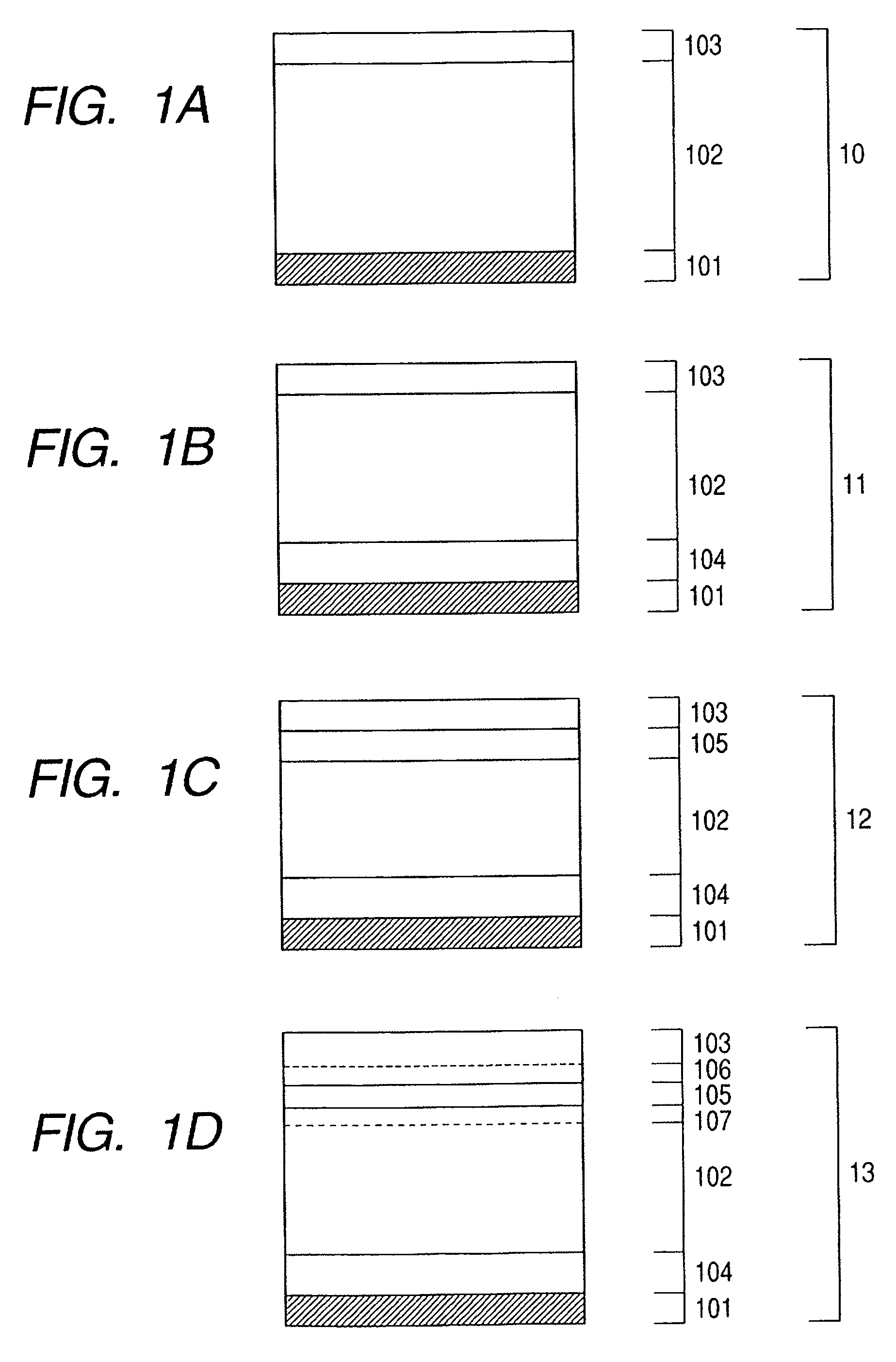
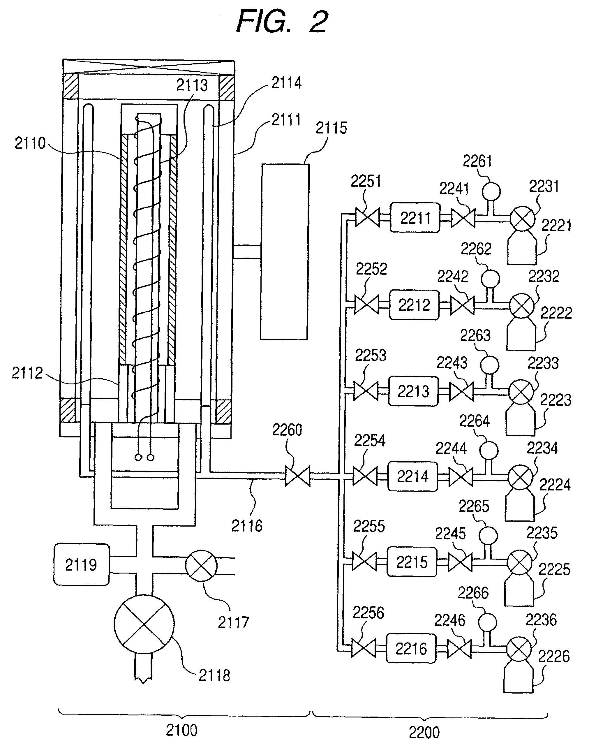
[0164]Using the plasma-assisted CVD system shown in FIG. 2, deposition films were successively formed and superimposed on mirror-finished aluminum cylinders (supports) of 84 mm in diameter under conditions shown in Table 1, to produce photosensitive members each including the lower-part charge injection blocking layer, photoconductive layer, upper-part charge injection blocking layer and surface layer shown in FIG. 1C. As to the lower-part charge injection blocking layer, the photoconductive layer, the upper-part charge injection blocking layer and the surface layer, films were all formed under the conditions shown in Table 1 as common conditions. In regard to the surface layer, SiH4 gas and N2 gas flow rates and electric power were changed as shown in Table 2 for each photosensitive member, to change the mixing ratio of SiH4 gas to N2 gas and the electric power per SiH4 gas quantity. As to other conditions, films were formed under the conditions shown in Table 1, to produce Photose...

example 2

[0170]Photosensitive Member G including the lower-part charge injection blocking layer, photoconductive layer, upper-part charge injection blocking layer and surface layer as shown in FIG. 1C was produced in the same manner as in Example 1 except that the conditions shown in Table 3 were applied. As shown in Table 3, when the surface layer was formed, CH4 gas and CO2 gas were fed so as to bring oxygen atom concentration and carbon atom concentration to appropriate values.

example 3

[0176]Five kinds of photosensitive members each including the lower-part charge injection blocking layer, photoconductive layer, upper-part charge injection blocking layer and surface layer shown in FIG. 1C were produced in the same manner as in Example 1 except that such conditions as shown in Table 5 were applied. The lower-part charge injection blocking layer, the photoconductive layer and the upper-part charge injection blocking layer were formed under the fixed conditions shown in Table 5, and the surface layer was formed changing the NO gas flow rate for each photosensitive member as shown in Table 6 and applying the conditions shown in Table 5, thereby producing Photosensitive Members J to N having different concentrations of oxygen atoms in the surface layers.


PUM


Abstract

An electrophotographic photosensitive member is provided which can keep at a minimum the absorption of image exposure light of 380 to 500 nm in wavelength in its surface layer and concurrently can satisfactorily keep electrophotographic properties including resolving power. The electrophotographic photosensitive member has a substrate, and a photoconductive layer and a surface layer in this order provided on the substrate. The surface layer includes an amorphous material composed chiefly of silicon atoms and nitrogen atoms and containing at least oxygen atoms and carbon atoms, and the ratios of the numbers of the respective oxygen atoms, carbon atoms and nitrogen atoms to the total number of oxygen atoms, carbon atoms and nitrogen atoms contained in the amorphous material are each within a specific range.

Description

[0001]This application is a continuation of International Application No. PCT / JP2005 / 020766, filed on Nov. 7, 2005, which claims the benefit of Japanese Patent Application Nos. as follows:[0002]1) 2004-322760 filed on Nov. 5, 2004[0003]2) 2004-322772 filed on Nov. 5, 2004BACKGROUND OF THE INVENTION[0004]1. Field of the Invention[0005]This invention relates to an electrophotographic photosensitive member and an electrophotographic apparatus making use of the same, and more particularly relates to an electrophotographic photosensitive member most suited for printers, facsimile machines, copying machines and so forth in which light of 380 nm or more to 500 nm or less in wavelength is used in exposure, and an electrophotographic apparatus making use of the same.[0006]2. Related Background Art[0007]In electrophotographic apparatus used as printers, facsimile machines, copying machines and so forth, a photosensitive member charged electrostatically by a charging member is irradiated with ...

Claims


Application Information

Patent Timeline
Patent Type & Authority Patents(United States)
IPC IPC(8): G03G5/147
CPCG03G5/08214G03G5/08235G03G5/14708G03G5/08278G03G5/0825
Inventor AOKI, MAKOTOKOJIMA, SATOSHIYAMADA, MOTOYAHOSOI, KAZUTOOHIRA, JUNOWAKI, HIRONORI
Owner CANON KK
Why Eureka
Try Eureka