Organic electroluminescence element and an exposure unit and image-forming apparatus both using the element

an organic electroluminescence element and exposure unit technology, applied in the direction of instruments, discharge tube luminescnet screens, electrographic processes, etc., can solve the problems of difficult to achieve full color emission, low efficiency of taking out actual emitted light into the air, and strong influence on emission light, so as to improve the emission light quantity of organic electroluminescence elements and alleviate damage during film formation

Active Publication Date: 2007-01-02
JOLED INC
View PDF23 Cites 141 Cited by
  • Summary
  • Abstract
  • Description
  • Claims
  • Application Information

AI Technical Summary

Benefits of technology

[0023]Since light emission takes place in a plurality of light emission layers in such apparatuses, the light quantity emitted by the organic electroluminescence element can be enhanced.
[0041]The invention set forth in Claim 16 provides an exposure unit in the invention set forth in Claim 15 in which the light emission layer arranged close to the anode and the light emission layer arranged close to the cathode are made of the same material, and has the capability of enabling the enhancement of the emission light quantity of the organic electroluminescence element.

Problems solved by technology

In addition, due to the difficulty in blue light emission, it is difficult to achieve full color emission based on the three primary colors of R, G and B. Moreover, since the refractive index of the material used as the light emitter of an inorganic electroluminescence element is very high, the emission light is strongly affected by the effect of the total reflection at boundaries.
Accordingly, the efficiency of taking out the actually emitted light into the air is as low as roughly 10 to 20%, which value is difficult to improve.
Though various investigations have been made, they never evolved to a full-scale study for practical use because the emission efficiency was extremely low.
In the case of laser beam exposure, downsizing of the unit is quite difficult since optical parts such as a polygon mirror or lenses occupy large spaces.
In the case of LED array exposure, cost reduction of the unit is difficult because the circuit board is expensive.
However, since the light emitted from the organic electroluminescence element is diffusive, it has been impossible to achieve a sufficient level of light quantity required to form an image on a photoreceptor with the diffusive light from the conventional element.

Method used


Image

  • Organic electroluminescence element and an exposure unit and image-forming apparatus both using the element
  • Organic electroluminescence element and an exposure unit and image-forming apparatus both using the element
  • Organic electroluminescence element and an exposure unit and image-forming apparatus both using the element

Examples


first embodiment

(First Embodiment)

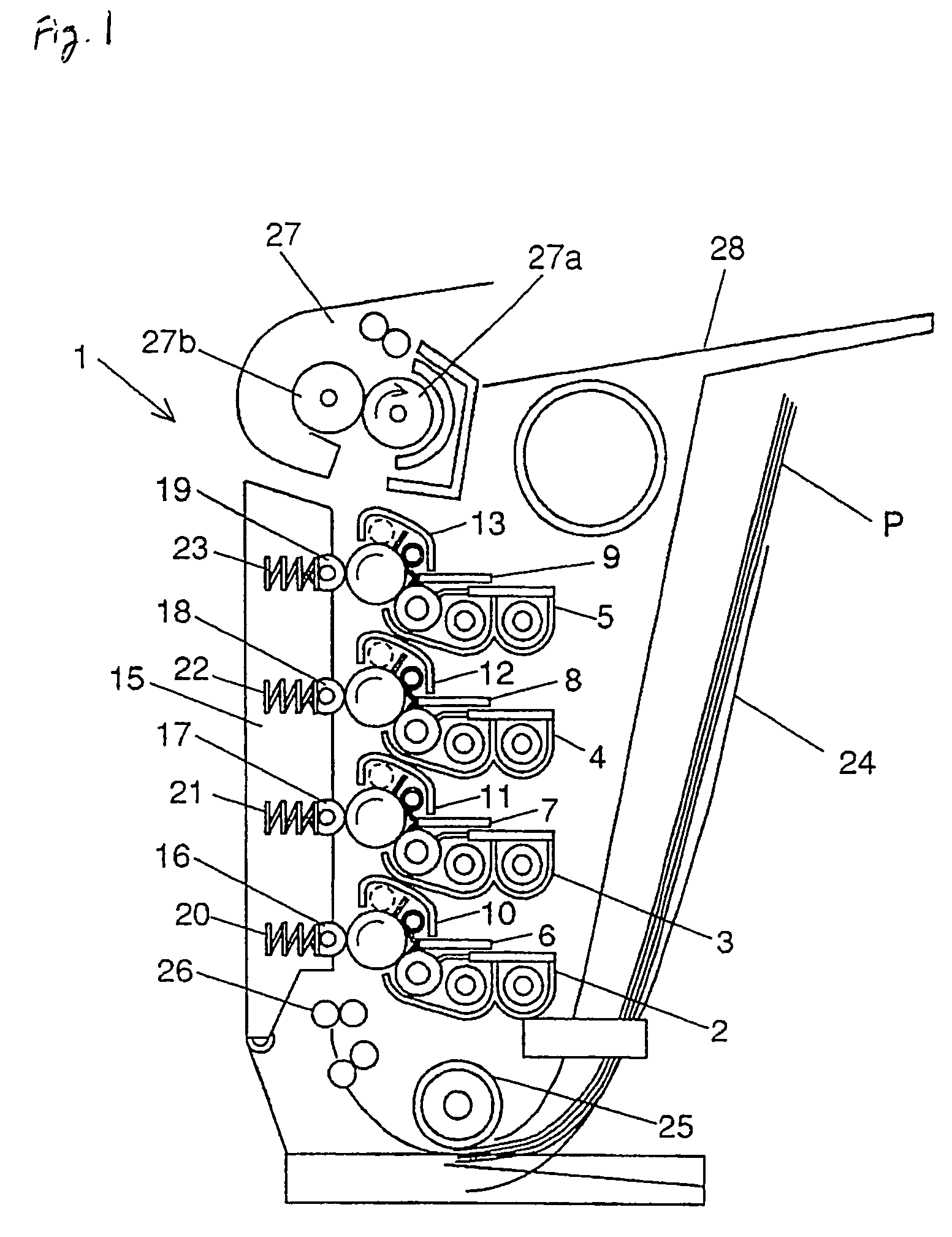
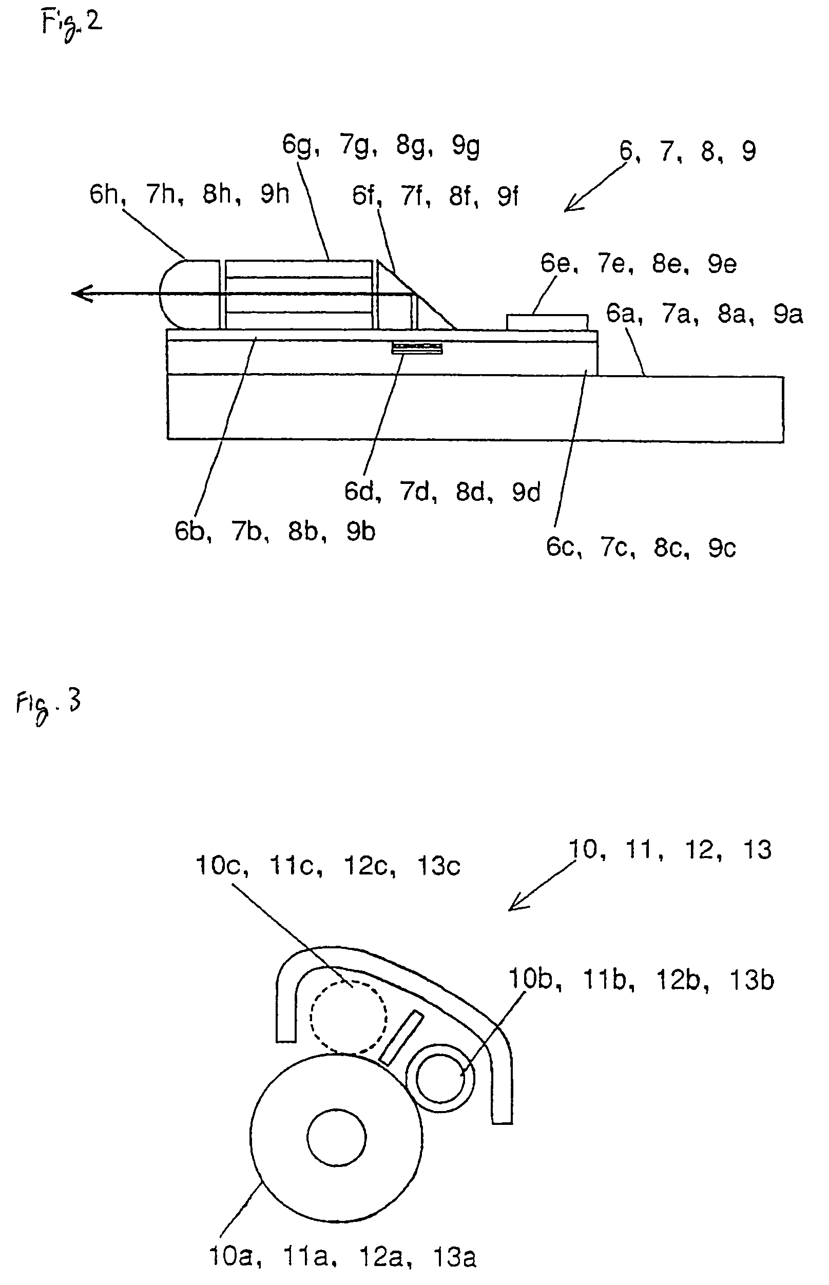
[0066]FIG. 1 is a schematic view showing the configuration of a color image-forming apparatus in the first embodiment of practicing the invention. FIG. 2 is an explanatory drawing showing in detail the exposure part of the color image-forming apparatus depicted in FIG. 1. FIG. 3 is an explanatory drawing showing in detail the photoreception part of the color image-forming apparatus depicted in FIG. 1. FIG. 4 is an explanatory drawing showing in detail the development part of the color image-forming apparatus depicted in FIG. 1. FIG. 5 is a cross-sectional view showing the essential part of an organic electroluminescence element used as the light source of the exposure part depicted in FIG. 2. And, FIG. 6 is a cross-sectional view showing the essential part of another modified example of the organic electroluminescence element used as the light source of the exposure part depicted in FIG. 2.

[0067]In FIG. 1, the color image-forming apparatus 1 is provided with develo...

second embodiment

(Second Embodiment)

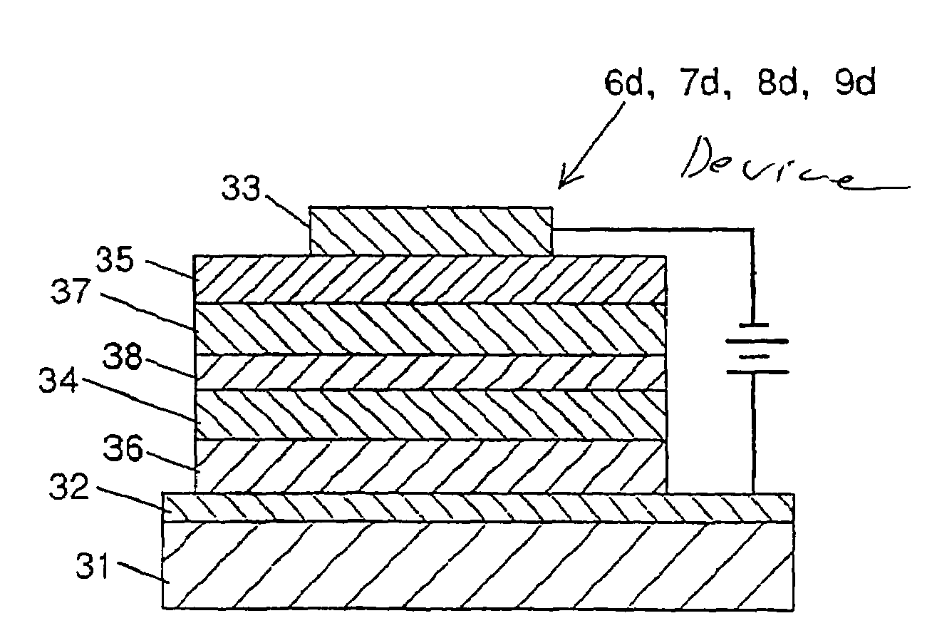
[0116]FIG. 7 is a cross-sectional view showing the essential part of an organic electroluminescence element used as the light source of the exposure part for the color image-forming apparatus in the second embodiment for practicing the invention. For confirmation, in the present embodiment, the configuration and the details of the color image-forming apparatus are the same as depicted in FIGS. 1 to 4 used in the first embodiment.

[0117]The depicted organic electroluminescence element as the exposure light source has a structure comprising, on a substrate 31, an anode 32, a first hole transport layer 36, a first light emission layer 34, a charge generation layer 38, a second hole transport layer 37, a second light emission layer 35, another charge generation layer 38, a third hole transport layer 36, a third light emission layer 34, still another charge generation layer 38, a fourth hole transport layer 37, a fourth light emission layer 35 and a cathode 33, all stac...

third embodiment

(Third Embodiment)

[0125]FIG. 22 is a cross-sectional view showing the essential part of an organic electroluminescence element used as the light source of the exposure part for the color image-forming apparatus in the third embodiment for practicing the invention. For confirmation, in the present embodiment, the configuration and the details of the color image-forming apparatus are the same as depicted in FIGS. 1 to 4 used in the first embodiment.

[0126]The depicted organic electroluminescence element as the exposure light source has a structure comprising, provided on a substrate 31, an anode 32, a first hole transport layer 36, a first light emission layer 34, a cathode 33, an insulating layer 39, an anode 32, a second hole transport layer 37, a second light emission layer 35 and another cathode 33, all stacked in turn. In other words, in the structure, the anodes 32 and the cathodes 33 are arranged alternately each with the intervening light emission layer 34 (35) and hole transpo...


PUM


Abstract

Providing an exposure unit using an organic electroluminescence element with a large emitted light quantity.The organic electroluminescence element has, on a substrate 31, an anode 32 acting as a hole injection electrode, a cathode 33 acting as an electron injection electrode, a first and second emission layers 34 and 35 each having a light emission region, and a charge generation layer 38 injecting electrons into the light emission layer 34 lying close to the anode 32 and injecting holes into the light emission layer 35 lying close to the cathode 33, these layers being arranged between the anode 32 and the cathode 33.

Description

BACKGROUND OF THE INVENTION[0001]1. Field of the Invention[0002]The present invention relates to an organic electroluminescence element used for a light emission device in various apparatuses and an exposure unit as well as an image-forming apparatus using the element.[0003]2. Description of the Related Art[0004]An electroluminescence element is a light emission device using electric field-induced light emission of a solid luminescent material. Now, inorganic electroluminescence elements that use inorganic materials as the light emitter are in practical use, and expansion of their applications to the backlight for liquid crystal displays or flat panel displays are intended in some segments. However, the voltage required for the light emission of inorganic electroluminescence elements is rather high, i.e., 100 v or higher. In addition, due to the difficulty in blue light emission, it is difficult to achieve full color emission based on the three primary colors of R, G and B. Moreover...

Claims


Application Information

Patent Timeline
Patent Type & Authority Patents(United States)
IPC IPC(8): B41J2/385B41J2/45H01L51/52H01L51/56H05B33/00
CPCH01L51/5278H01L51/56H10K50/19H10K71/00
Inventor GYOUTOKU, AKIRAHAMANO, TAKAFUMITOYOMURA, YUJINAKAMURA, TETSUROMASUMOTO, KENICHIYAMAMOTO, SHINYA
Owner JOLED INC
Why Eureka
Try Eureka