
Motion picture encoding apparatus

a motion picture and encoding technology, applied in the field of motion picture encoding apparatus, can solve the problems of increasing the amount of operation for detecting the motion vector, changing the compression accordingly, and changing the image quality of the motion picture provided to the user

Inactive Publication Date: 2007-01-02
SONY CORP
View PDF18 Cites 33 Cited by
  • Summary
  • Abstract
  • Description
  • Claims
  • Application Information

AI Technical Summary

Benefits of technology

The present invention relates to a motion picture encoding apparatus for compressing and distributing motion picture data by using the Internet. The apparatus uses the MPEG2 standard for compression encoding, which is a combination of motion compensation predictive encoding and discrete cosine transformation. The apparatus sequentially assigns any of the I-picture, P-picture, and B-picture to frame image data in a predetermined order, and records picture type information representing the I-picture, P-picture, and B-picture by associating it with the frame image data. The apparatus then reads the first frame image data and sends it to a discrete cosine transformer for discrete cosine transformation, followed by a quantizer and a dequantizer for quantization and dequantization, and a motion compensator for motion compensation. The encoded data is then output to the outside via a buffer. The technical effect of the invention is to provide a more efficient and effective method for compressing and distributing motion picture data over the Internet.

Problems solved by technology

According to this method, however, the frame image data is merely excluded from the motion picture data at the predetermined intervals, irrespective of change in the picture of the motion picture, which has a problem that, if the picture of the motion picture remarkably changes between the frame image data remaining after the exclusion, the compressibility changes accordingly and so the image quality of the motion picture provided to the user consequently changes.
Thus, this method has a problem in that, because the motion vector of the macro-block data is detected for each the tracing and compression encoding of the extract image data, the amount of operation for detecting the motion vector increases and as a result, the compression encoding of the extract image data needs a lot of processing time.

Method used


Image

  • Motion picture encoding apparatus
  • Motion picture encoding apparatus
  • Motion picture encoding apparatus

Examples


first embodiment

(2) FIRST EMBODIMENT

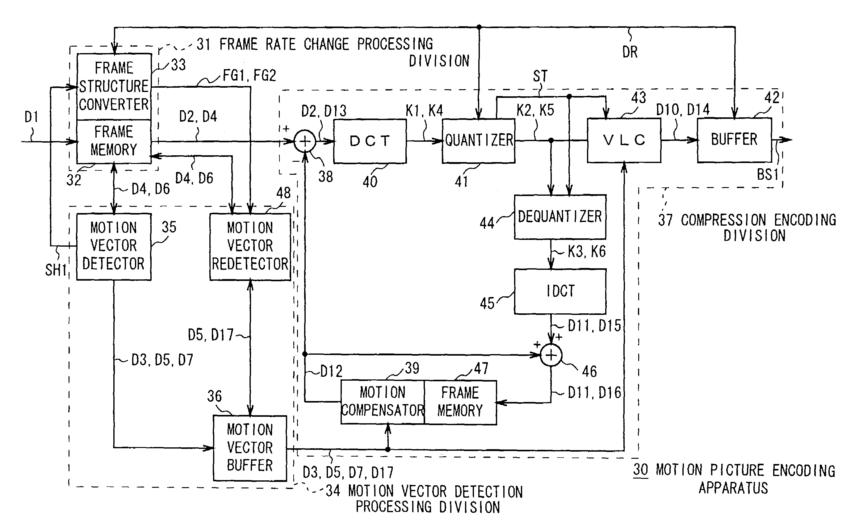
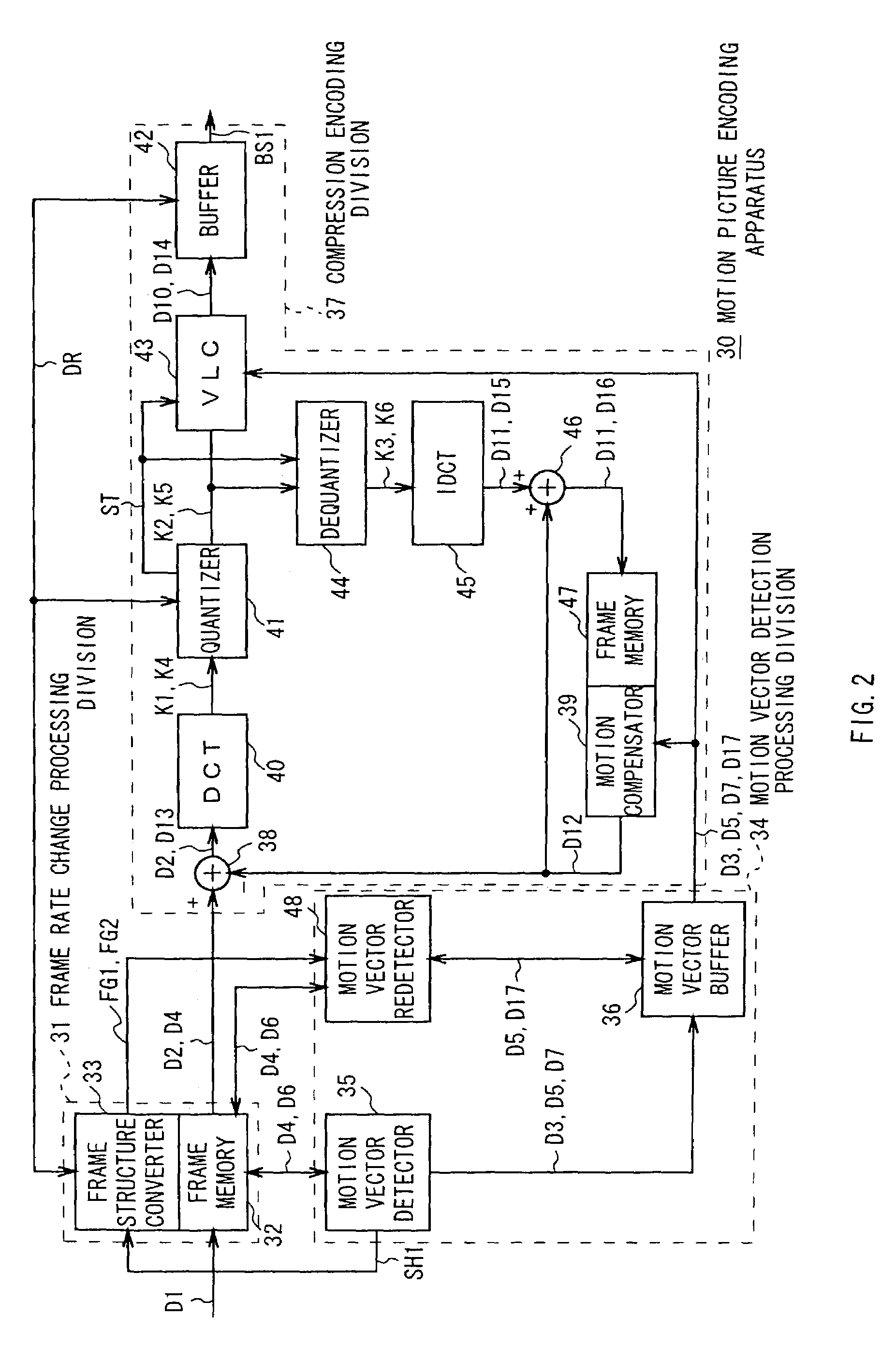
[0118]In FIG. 2, reference numeral 30 denotes the motion picture encoding apparatus according to the first embodiment as a whole, where motion picture data D1 supplied from an external video camera (not shown) shooting an object (not shown) is sequentially captured on a frame image data basis into a frame memory for inputting 32 having recording capacity of a plurality of frames, provided in a frame rate change processing division 31.

[0119]In this case, as shown in FIG. 3, every time the frame image data is captured into the frame memory for inputting 32, a frame structure converter 33 of the frame rate change processing division 31 assigns picture types such as an I-picture and a P-picture to the captured frame image data in an order wherein one I-picture and a predetermined number of P-pictures are sequentially and alternately successive, and also records in the frame memory for inputting 32 the picture types representing the I-picture and the P-picture and fra...

second embodiment

(3) SECOND EMBODIMENT

[0242]FIG. 10 in which the same reference numerals are applied to parts corresponding to those in FIG. 2 shows a motion picture encoding apparatus 60 according to a second embodiment, which is constructed in the same way as the motion picture encoding apparatus 30 according to the first embodiment, except the constructions of a frame structure converter 62 of a frame rate change processing division 61 and a motion vector detection processing division 63.

[0243]As in the case mentioned above about FIG. 3, every time the frame image data is captured into the frame memory for inputting 32, the frame structure converter 62 of the frame rate change processing division 61 assigns the picture types, the I-picture and the P-picture, to the captured frame image data and also records in the frame memory for inputting 32 the picture types each representing the I-picture or the P-picture and the frame identification information unique to the frame image data to which the pic...

third embodiment

(4) THIRD EMBODIMENT

[0311]FIG. 15 in which the same reference numerals are applied to parts corresponding to those in FIG. 10 shows a motion picture encoding apparatus 70 according to a third embodiment, which has the same construction as the motion picture encoding apparatus 60 according to the second embodiment, except the constructions of a motion vector detection processing division 71, a compression encoding division 72 and a mask image processing division 73.

[0312]In the motion vector detection processing division 71, when the I-picture is assigned to the leading frame image data constituting the motion picture data D1 in the frame memory for inputting 32, a simple motion vector detector 74 reads the picture information on the first frame image data to which the I-picture is assigned and thereby generates the predictive mode data D3 based on the picture information, and then sends the generated predictive mode data D3 to a simple motion vector buffer 75 to accumulate it therei...


PUM


Abstract

Motion picture data is compression-encoded by a compression encoder with the frame rate changing according to the amount of accumulated data of the buffer, which can adequately change the number of pieces of frame image data to be compression-encoded per unit time, according to the change in the picture of the motion picture. In addition, tracing is done to trace extract image data in the frame image data by using a simple motion vector detected for the frame image data of the motion picture data, a higher layer motion vector detector detects a motion vector of the frame image data by using the simple motion vector in common, and a compression encoder extracts the extract image data based on the results of tracing and compression-encodes it by using the motion vector.

Description

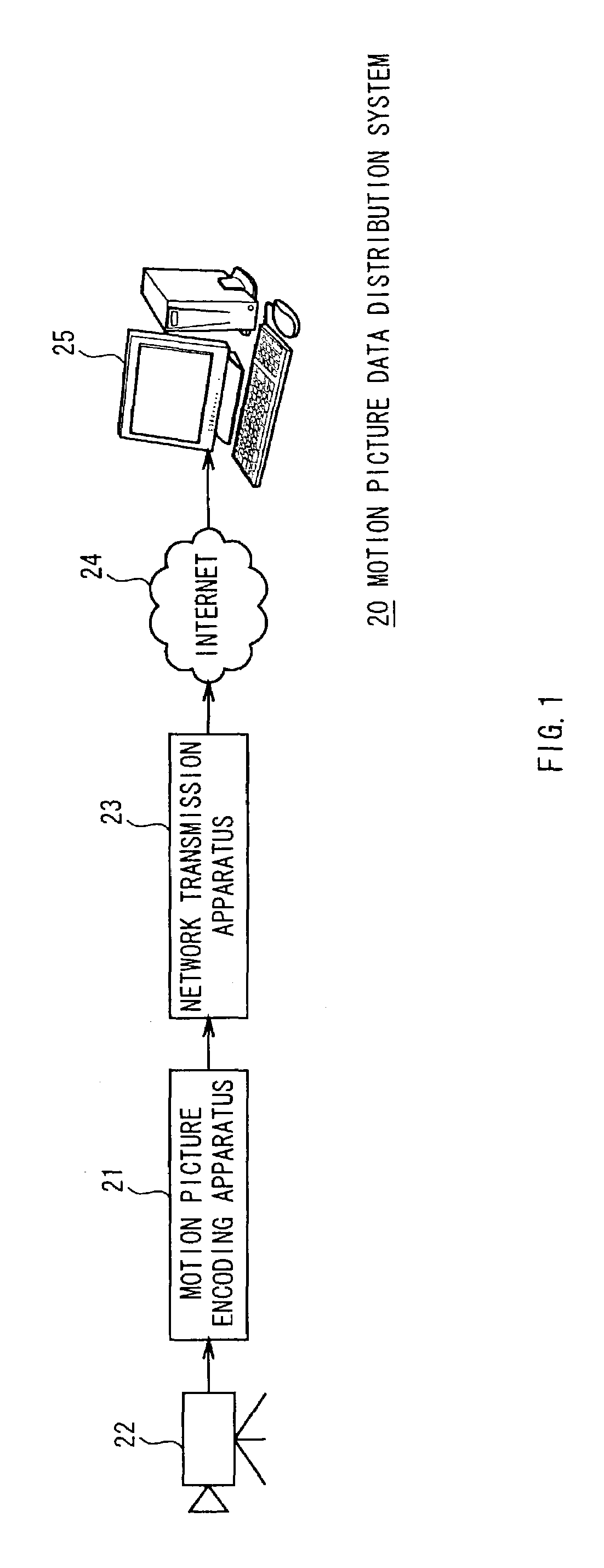
TECHNICAL FIELD[0001]The present invention relates to a motion picture encoding apparatus, and is suitably applied to, for instance, a motion picture encoding apparatus for compression-encoding motion picture data when distributing the motion picture data by using the Internet.BACKGROUND ART[0002]In recent years, a distribution method generally called streaming has started to spread as a method of distributing motion picture data by using the Internet, wherein motion picture data which is obtained while an object is shot with a video camera or the like is sent to a user's personal computer or the like via the Internet so as to show motion picture based on the motion picture data in real time.[0003]As for such a distribution method by streaming, a data transfer rate of the Internet is relatively low, and so a motion picture encoding apparatus to which a compression encoding method called MPEG2 (Moving Picture Experts Group phase 2) is applied, for instance, is provided on a sender si...

Claims


Application Information

Patent Timeline
Patent Type & Authority Patents(United States)
IPC IPC(8): H04B1/66G06T9/00H04N19/132H03M7/30H03M7/40H04N19/134H04N19/137H04N19/139H04N19/15H04N19/172H04N19/196H04N19/423H04N19/50H04N19/503H04N19/51H04N19/53H04N19/543H04N19/587H04N19/593H04N19/61H04N19/625H04N19/85H04N19/91
CPCH04N19/105H04N19/139H04N19/172H04N19/51H04N19/587H04N19/61H04N19/132H04N19/152H04N19/17H04N19/115H04N19/15
Inventor NAGUMO, TAKEFUMIYASUDA, HIROYUKIMITSUHASHI, SATOSHIANDO, YUJIKOJIMA, TAKASHIZHU, YIWEN
Owner SONY CORP
Learn More