Smart amplifier for time division duplex wireless applications

Inactive Publication Date: 2007-01-02
TELECTRONICS INT
View PDF17 Cites 3 Cited by
  • Summary
  • Abstract
  • Description
  • Claims
  • Application Information

AI Technical Summary

Benefits of technology

[0008]It is another object of this invention to provide an amplifier maximizing operational capabilities so as to be usable in a broad range of situations and adapted for use over a wide input power range.
[0010]Still another object of this invention is to provide a standardized amplifier structure which is economical to install and to maintain.
[0013]A further object of this invention is to maintain constant power levels and minimize signal distortion.
[0018]The invention is particularly a cost effective solution for “last-mile” applications, e.g. connectivity between office buildings, for remote monitoring and in rural areas. Presently, the invention is designed for use with direct sequence or frequency hopping spread spectrum radio modems (or wireless equipment such as LAN cards) to boost transmit power amplification and receive signal gain. By including a dynamic power sensor in an amplifier constructed according to the invention, the RF power output level is adjusted by detecting the input signal power. This automatic gain adjustment minimizes distortion and maximizes output power regardless of variations in input levels.
[0019]By exploiting the automatic gain control technique of the invention, an antenna amplifier can detect the input power level, automatically adjust its gain, maintain the output power to a specified level, minimize the signal distortion, and maximize transmission distance. Moreover, standardization, simplicity, and low cost, give this invention an advantage over conventional, “non-intelligent” amplifier structures and methods, particularly as applied to TDD wireless applications.

Problems solved by technology

In many such instances, the use of conventional amplifiers is limited and a single amplifier design cannot and does not have a sufficient useful range to meet many typical applications.
Failure to exercise careful installation and engage in proper maintenance can cause serious operational degradation.

Method used


Image

  • Smart amplifier for time division duplex wireless applications
  • Smart amplifier for time division duplex wireless applications
  • Smart amplifier for time division duplex wireless applications

Examples


Embodiment Construction

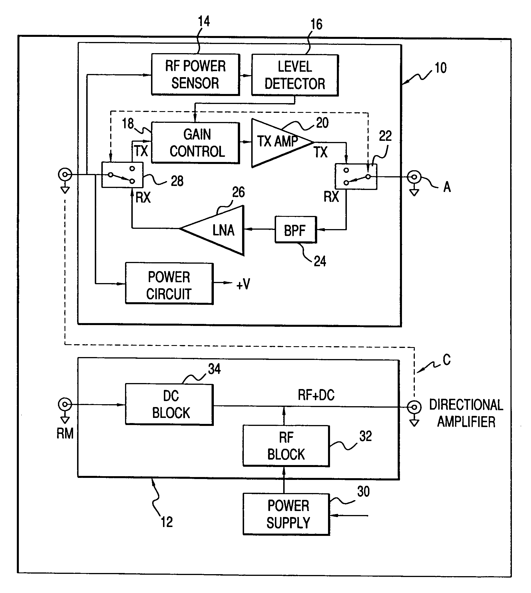
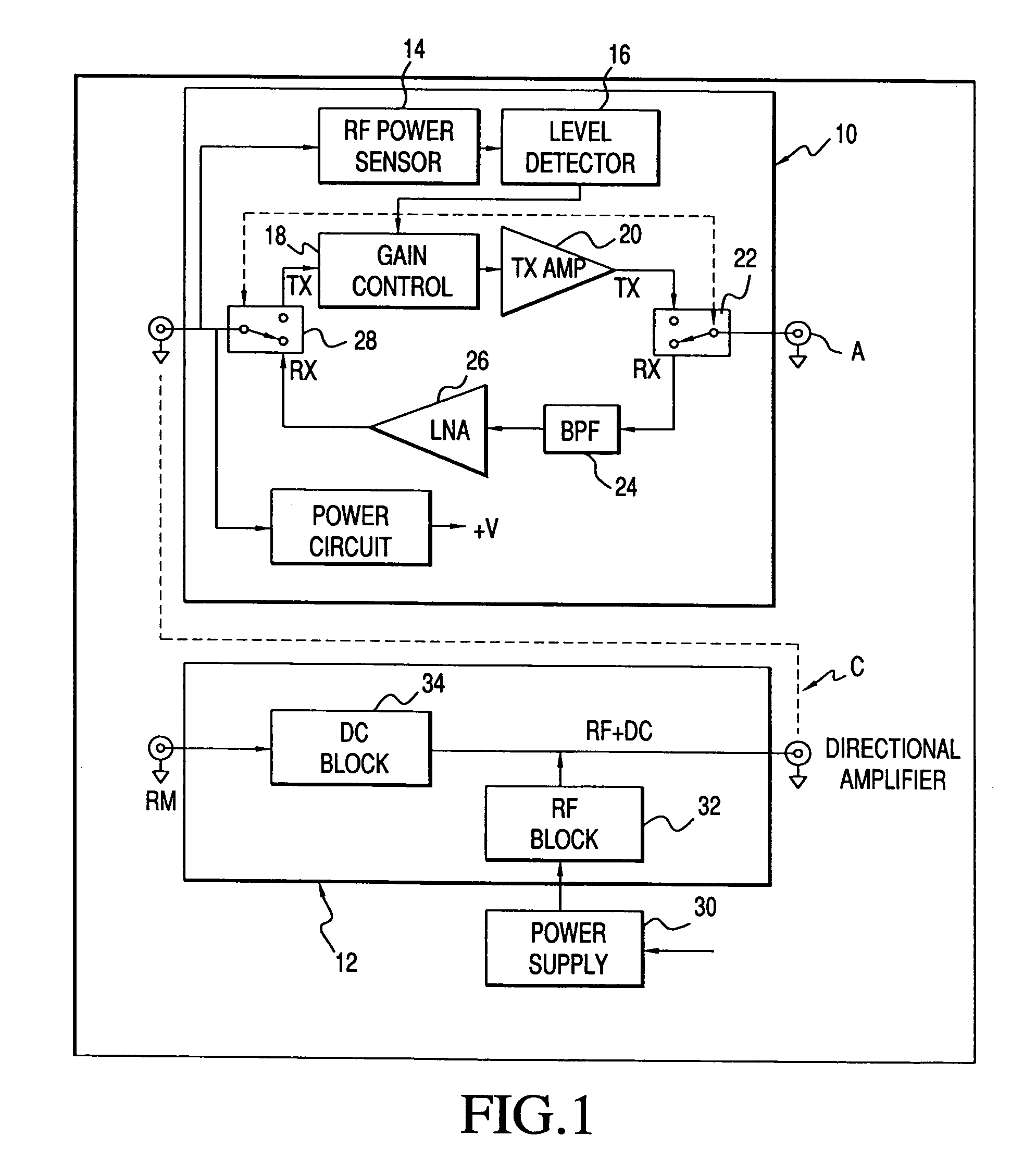
[0028]As illustrated in functional block diagram FIG. 1, the invention comprises a bi-directional amplifier unit 10 connected to an antenna A and a DC Injector unit 12 via a bi-directional cable C (communicating RF signal and DC power to antenna amplifier) where the DC injector is connected to a wireless radio unit which for the purposes of illustration and not limitation is identified as a radio modem RM herein. The amplifier includes a power detection module comprising an RF power sensor 14 and a power level detector 16. The power level detector 16 connects to a variable attenuator gain control module 18, the output of which is fed to a transmitting amplifier 20 which in turn amplifies its output to a transmit / receive switch 22. The switch 22 operatively connects the amplifier unit to the RF antenna A and also toggles between a transmitting mode and receiving mode. When in a receiving mode, the switch directs the antenna input to a bandpass filter 24 followed by a low-noise amplif...


PUM


Abstract

A bi-directional antenna-mount amplifier particularly suited to be compatible with a broad range of advanced spread spectrum TDD wireless applications relying on either direct sequence or frequency hopping, at a wide range of frequencies, and which allows the radio device sharing of an associated antenna in different time intervals, where signal distortion is minimized due to operation of the amplifier which is governed by an equation and associated gain control circuits to maintain constant output power and prevent transmit signal saturation.

Description

[0001]This application claims priority to Provisional Application Ser. No. 60 / 124,365 filed Mar. 15,1999 and is a divisional of application Ser. No. 09 / 524,745 filed Mar. 14, 2000, now U.S. Pat. No. 6,681,100.BACKGROUND OF THE INVENTION[0002]1. Technical Field[0003]This invention relates to wireless applications using Time Division Duplex (TDD) technology in Wireless Local Area Network (WLAN), Wireless Local Loop (WLL), Wireless Internet Access (WIA), wireless modem connection with point-to-point and point-to-multipoint applications.[0004]2. Description of the Related Art[0005]Typically in wireless applications, adding on an antenna amplifier and DC injector is a purchaser option. However, when the operating range of wireless applications is long as, for example, between buildings on a campus, the inclusion of an add-on antenna amplifier / DC injector set may become necessary in order to preserve transmission quality. As is well known by persons in the art, every system presents its o...

Claims


Application Information

Patent Timeline
IPC IPC(8): H04B1/44H03G3/30H04B1/38H04B1/48H04B1/56
CPCH03G3/3042H04B1/56H04B1/48H04B1/3877
Inventor GE, DAVID
Owner TELECTRONICS INT
Why Eureka
Try Eureka