Shape-based geometry engine to perform smoothing and other layout beautification operations

a geometry engine and layout technology, applied in the field of integrated circuit layouts, can solve problems such as layout imperfections, adversely affecting layout printability or device performance, and polygons that make up the actual ic layout might include unintended irregularities, and achieve the effect of efficient layout beautification

Active Publication Date: 2007-01-02
SYNOPSYS INC
View PDF51 Cites 296 Cited by
  • Summary
  • Abstract
  • Description
  • Claims
  • Application Information

AI Technical Summary

Benefits of technology

[0009]The present invention provides a system for efficiently performing layout beautification on an IC layout (or a portion of an IC layout). In accordance with an embodiment of the invention, a layout beautification system uses a shape-based identification algorithm. A shape is defined as a set of associated edges and vertices, and therefore can provide much greater control and flexibility in identifying and correcting layout imperfections than can the conventional sizing up or down of the layout edges. A set of shapes can be defined and various corrective actions can be associated with those shapes. Shapes can include various contiguous edge profiles, such as notches, bulges, reverse hammerheads, and stair-steps, among others. Shapes can also include non-contiguous edge combinations, edges from multiple layers of an IC layout, and edges with specific properties.
[0011]In accordance with an embodiment of the invention, a shape-based layout beautification system can use a sequential processing algorithm. In accordance with another embodiment of the invention, a shape-based layout beautification system can use a concurrent processing algorithm, in which the entire set of shape-based actions are applied to an IC layout polygon in a single pass. The IC layout is therefore scanned just once, and the overhead associated with sequential processing due to the passing back and forth of intermediate layout data can be eliminated.
[0012]In accordance with another embodiment of the invention, the set of actions for a concurrent processing layout beautification system can be compiled in a look up table (LUT). A LUT is typically used to reduce processing times for applications involving the selection of a particular item from a large set of options. Because a table lookup can generally be performed substantially faster than a linear search for the applicable action, use of a LUT significantly reduces the total time required for layout beautification over conventional systems.
[0013]According to an embodiment of the invention, a layout beautification system includes an input data manager for receiving a layout data file, a layout beautification engine for applying the actions to the layout, and an output data manager for generating the corrected layout data file. In an embodiment of the invention, layout data files, shapes, and actions can be stored and accessed across a network, such as a LAN or a WAN. According to another embodiment of the invention, the input data manager can process and structure the layout data file for optimal processing by the layout beautification engine.

Problems solved by technology

However, while automated tools enable the accurate creation of IC layouts, the complex interactions of the rules embodied in those tools can result in layout imperfections.
In other words, while the results of an automated tool may be electrically correct (and even optically correct), the polygons that make up the actual IC layout might include unintended irregularities.
However, these layout imperfections may adversely affect layout printability or device performance.
Also, such imperfections can significantly increase data volume for a particular IC layout, thereby undesirably increasing layout processing (e.g., OPC, DRC, etc.) and mask production times.
Unfortunately, due to the complexity of modern IC layouts, detecting and correcting this type of layout imperfection (a technique sometimes referred to as “layout beautification”) can be difficult.
However, this technique of oversizing and undersizing provides a very limited solution to the problem of layout imperfections.
Because the manipulations are applied to the entire polygon, specific layout imperfections cannot be targeted and unintended (undesirable) modifications can occur.
Furthermore, this technique can only work on certain very simple layout imperfections.
Layout imperfections that are even marginally more complex cannot be corrected in this manner.
Consequently, layout data file sizes are unnecessarily large and processing of those data files (e.g., OPC, DRC, etc.) is unnecessarily time-consuming.
Furthermore, the excess of layout imperfections in conventional layouts also can cause problems during mask production by increasing the complexity of the mask-writing process (i.e., the creation of the mask pattern on the mask substrate).
This not only slows manufacturing throughput, but also increases the chances of errors during mask production.

Method used


Image

  • Shape-based geometry engine to perform smoothing and other layout beautification operations
  • Shape-based geometry engine to perform smoothing and other layout beautification operations
  • Shape-based geometry engine to perform smoothing and other layout beautification operations

Examples


Embodiment Construction

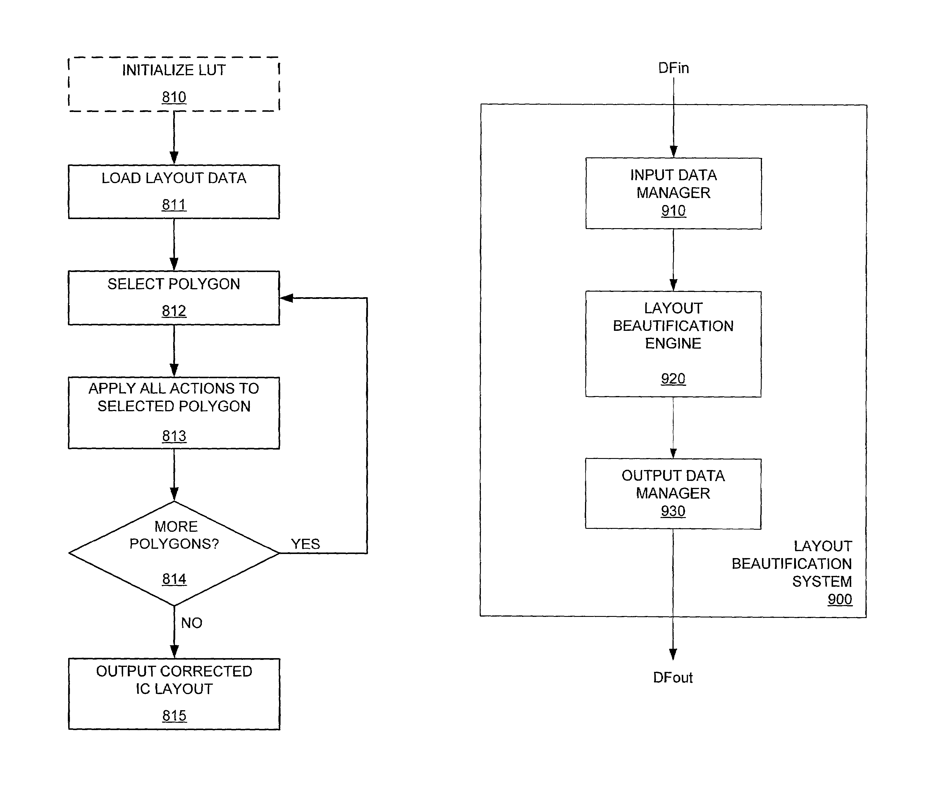
[0028]An embodiment of the invention provides a system and method for performing layout beautification on an IC layout using a shape-based approach. The shape-based approach advantageously enables accurate and efficient identification and correction of undesirable layout imperfections.

Shape Definition

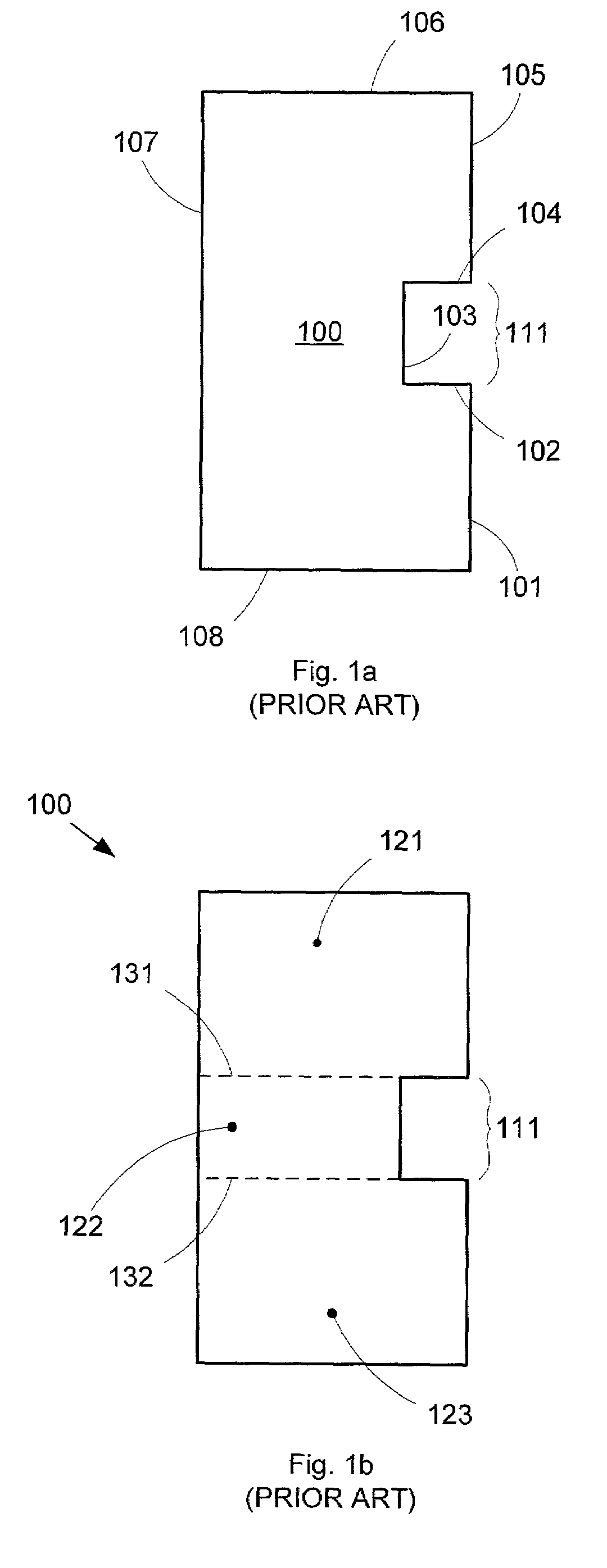
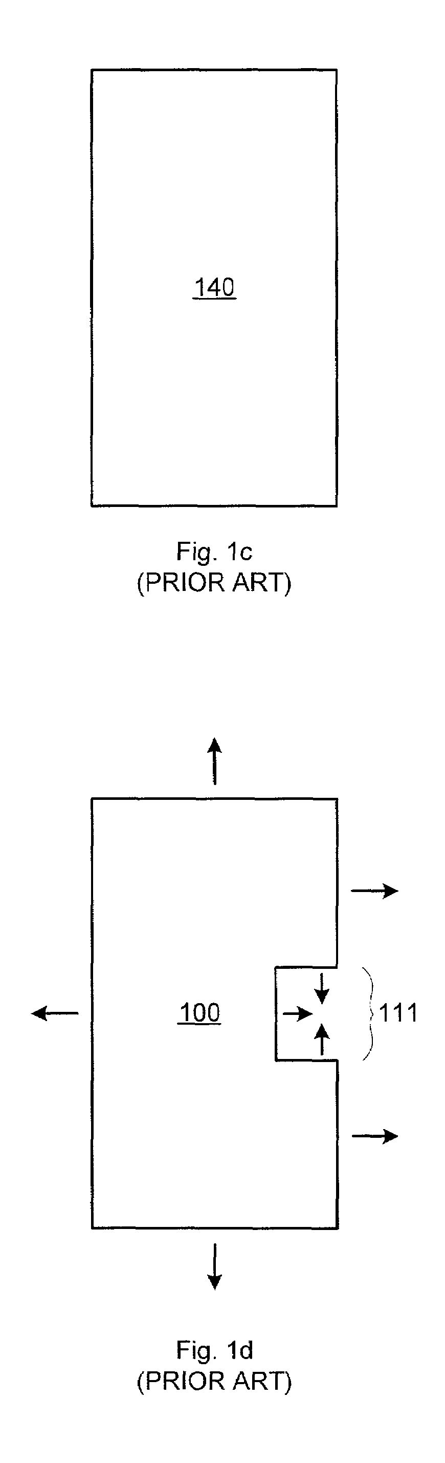
[0029]In accordance with embodiments of the invention, “shapes” can be defined as groupings of associated directed edges and vertices (i.e., points at which two directed edges meet). The direction of an edge determines which side (left or right) of the edge faces the inside or outside of the shape. For example, FIG. 2a shows a sample shape 200 that comprises a series of directed edges 201–208. Shape 200 has a substantially rectangular outline, with edges 202–204 forming a small notch 211 in one side of shape 200. The counter-clockwise direction of edges 201–208 means that the left sides of edges 201, 203, and 205 face the inside of shape 200.

[0030]Each shape represents a type of feature...


PUM

PropertyMeasurementUnit
angleaaaaaaaaaa
angleaaaaaaaaaa
lengthaaaaaaaaaa

Abstract

A shape-based layout beautification operation can be performed on an IC layout to correct layout imperfections. A shape is described by edges (and vertices) related according to specified properties. Each shape can be configured to match specific layout imperfection types. Corrective actions can then be associated with the shapes, advantageously enabling efficient formulation and precise application of those corrective actions. Corrective actions can include absolute, adaptive, or replacement-type modifications to the detected layout imperfections. A concurrent processing methodology can be used to minimize processing overhead during layout beautification, and the actions can also be incorporated into a lookup table to further reduce runtime. A layout beautification system can also be connected to a network across which shapes, actions, and IC layout data files can be accessed and retrieved.

Description

FIELD OF THE INVENTION[0001]The invention relates to the field of integrated circuit layouts, and more particularly to a system for removing imperfections from an integrated circuit layout.BACKGROUND OF THE INVENTION[0002]An integrated circuit (IC) is typically made up of many interconnected devices (e.g., transistors) formed on a silicon substrate. The layout of these devices and the manner in which they are interconnected determines the functionality of the IC. As modern ICs become ever more complex, automated design tools have become an essential part of the IC layout development process.[0003]Automated design tools can be used to perform various operations on an IC layout. For example, an automated tool might be used to make optical proximity correction (OPC) modifications or perform design rule checking (DRC) on an IC layout. An automated tool could even be used to create the actual IC layout from a design netlist.[0004]However, while automated tools enable the accurate creatio...

Claims


Application Information

Patent Timeline
Patent Type & Authority Patents(United States)
IPC IPC(8): G06F17/50G03C5/00G03F1/00G03F1/36
CPCG03F1/144G06F17/5081G03F1/36G06F30/398
Inventor FALBO, JAMES K.MALHOTRA, VINOD K.BALASINGAM, PRATHEEPZULCH, DONALD
Owner SYNOPSYS INC
Why Eureka
Try Eureka