Blood pump system

a pump system and pump technology, applied in the direction of positive displacement liquid engines, prosthesis, therapy, etc., can solve the problems of inability to arithmetically calculate or detect backflow, and achieve the effect of improving the condition of backflow generation

Active Publication Date: 2007-01-09
TC1 LLC
View PDF7 Cites 52 Cited by
  • Summary
  • Abstract
  • Description
  • Claims
  • Application Information

AI Technical Summary

Benefits of technology

[0015]The blood pump system may include a rotational speed control function for increasing the rotational speed of the rotor when it is determined by the backflow detecting function that a backflow is present. In this case, it is possible to improve the backflow generation condition.

Problems solved by technology

However, in a negative-flow-rate zone (the conditions for backflow), it is impossible to arithmetically calculate, or detect, the backflow by use of the flow rate operation expression which is prepared for a positive-flow-rate zone.

Method used


Image

  • Blood pump system
  • Blood pump system
  • Blood pump system

Examples


Embodiment Construction

[0034]Now, one embodiment of the blood pump system according to the present invention will be described.

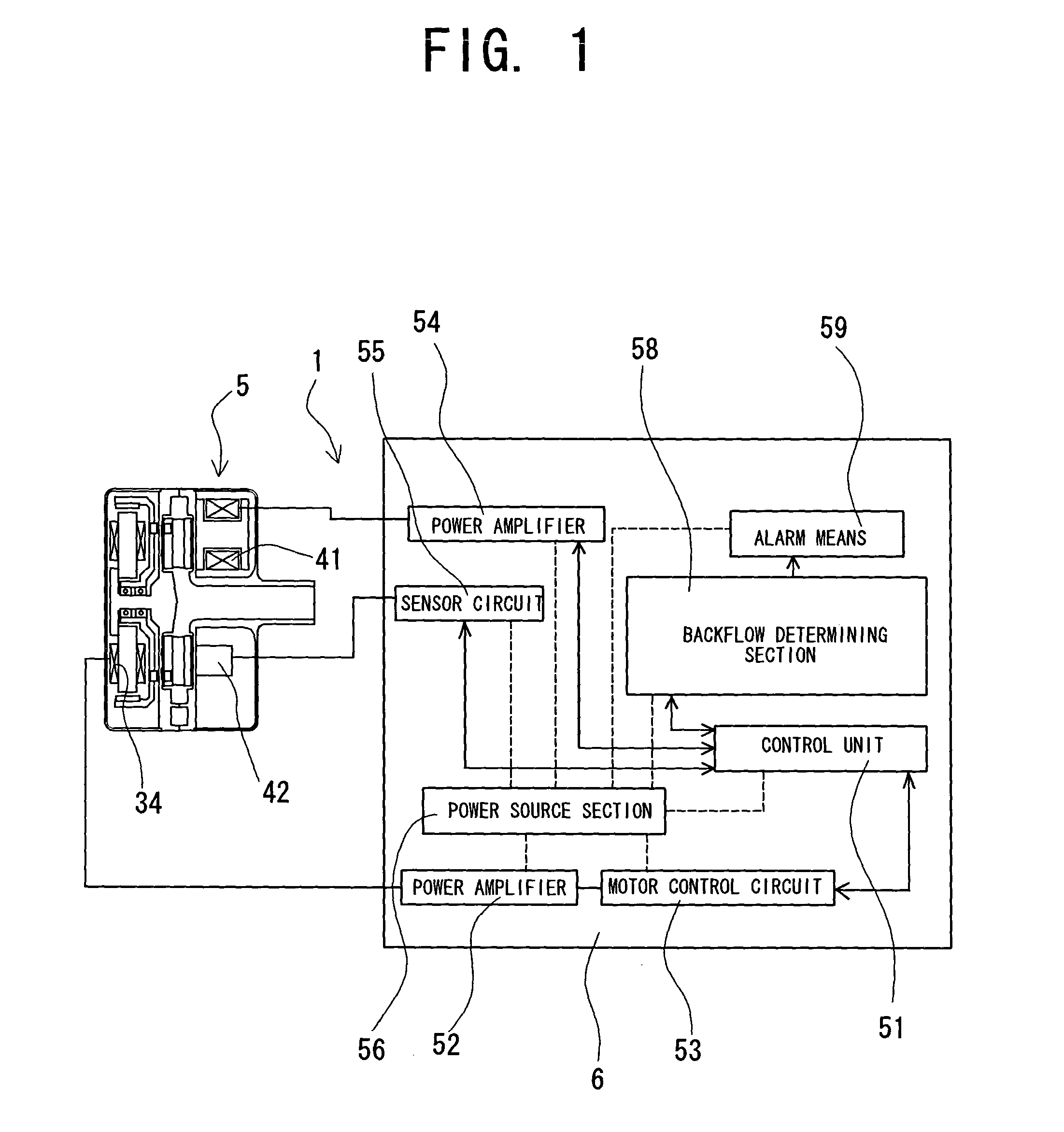
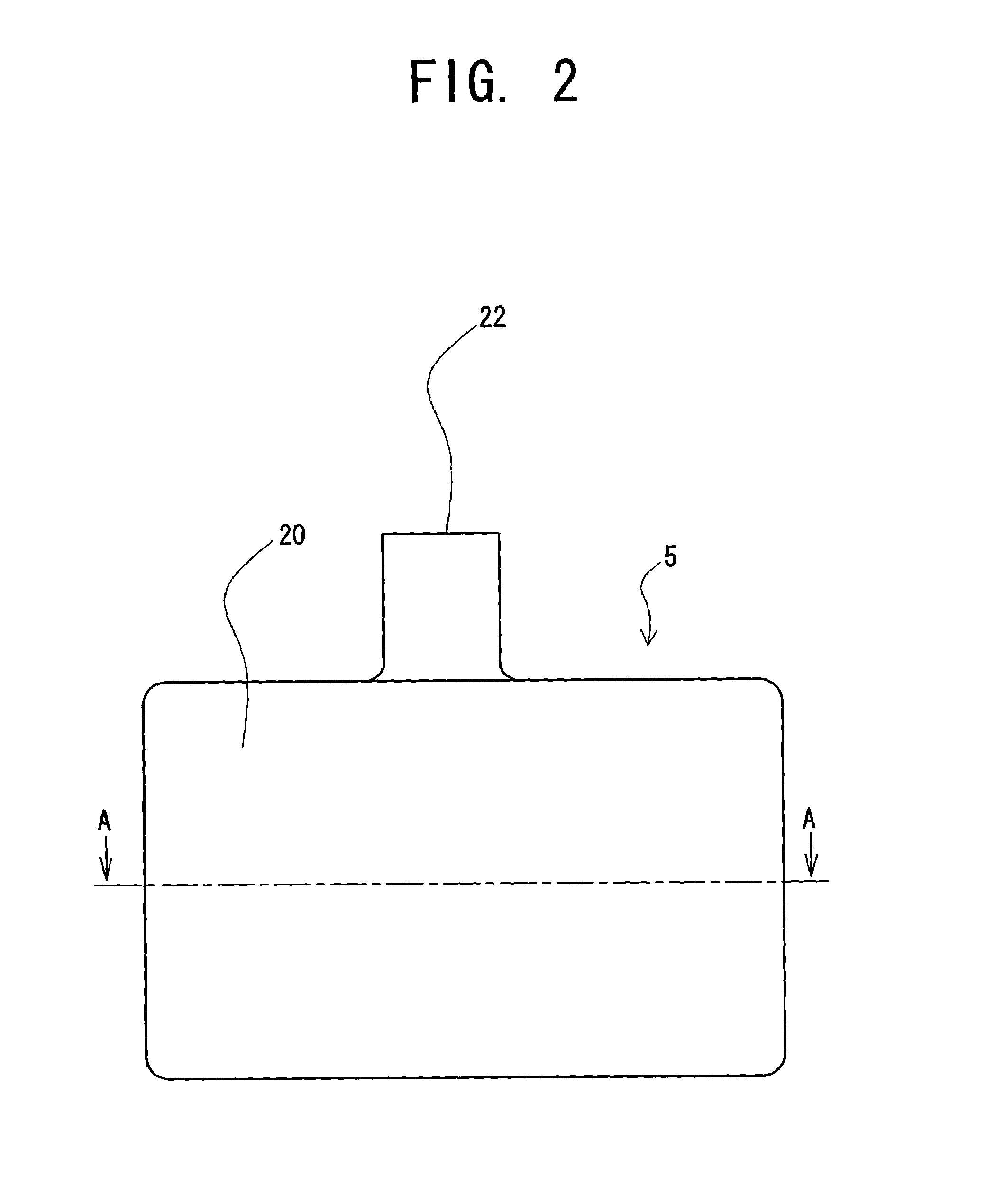
[0035]FIG. 1 is a block diagram of one embodiment of the blood pump system according to the present invention. FIG. 2 is a front view of one example of a blood pump system main body portion used in the blood pump system according to the present invention. FIG. 3 is a plan view of the blood pump system main body portion shown in FIG. 2. FIG. 4 is a vertical sectional view of the blood pump system main body portion according to the embodiment shown in FIG. 2. FIG. 5 is a sectional view taken along line A—A of FIG. 2.

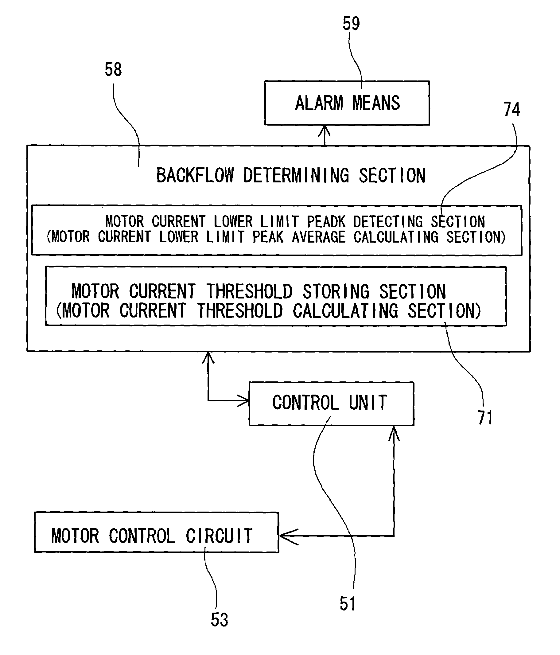
[0036]The blood pump system 1 according to the present invention comprises a housing 2 having an inlet port 22 and an outlet port 23, a rotor 21 rotated in the housing 2 for pumping blood, and a motor 34 for rotating the rotor 21. The blood pump system 1 comprises a motor current measuring function, and a backflow detecting function for detecting a backflow of blood by u...


PUM


Abstract

A blood pump system includes a housing having an inlet port and an outlet port, a rotor rotated in the housing for pumping blood, and a motor for rotating the rotor. The blood pump system includes a motor current measuring function, and a backflow detecting function for detecting a backflow of blood by use of the motor current value continuously measured by the motor current measuring function.

Description

BACKGROUND OF THE INVENTION[0001]The present invention relates to a blood pump system for pumping blood as a continuous flow.[0002]In recent years, development of continuous flow type blood pumps as artificial heart units has been conducted energetically. A general example of continuous flow type blood pump is the one of the type in which an impeller is rotated by a motor to thereby pump blood. Another example is a so-called axial flow pump in which a shaft is rotated by a motor to thereby pump blood. For measuring the blood flow rate in these pumps, there may be considered the following two methods:[0003](1) To attach a flow rate sensor.[0004](2) To calculate the flow rate from information on the motor.[0005]The method of (1) is advantageous in that accurate flow rate measurement can be achieved, while the method of (2) is advantageous in that it is needless to provide a flow rate sensor and, hence, it is possible to reduce the apparatus in size and to reduce power consumption. The...

Claims


Application Information

Patent Timeline
Patent Type & Authority Patents(United States)
IPC IPC(8): A61N1/362A61M1/10F04B49/10A61M1/12F04D15/02
CPCA61M1/101F04D15/02A61M1/122F04D15/0236A61M1/1015F04D15/0209A61M2205/3334A61M60/419A61M60/148A61M60/546A61M60/806A61M60/816A61M60/237A61M60/178A61M60/232A61M60/422
Inventor YANAI, MASAMICHI
Owner TC1 LLC
Why Eureka
Try Eureka