Operation checking device and checking method for dispenser

Inactive Publication Date: 2007-01-09
PRECISION SYST SCI +1
15 Cites 6 Cited by

AI-Extracted Technical Summary

Problems solved by technology

Furthermore, in the case where a process is carried out by automated equipment that performs a series of operations sequentially and automatically, after the series of operations finishes, th...

Benefits of technology

[0101]In the thirty-eighth aspect of the invention, an effect as alread...

Abstract

An object is to provide a dispenser operation verification apparatus and verification method that enables operation with high reliability and high accuracy.
The construction is such that with a dispenser comprising: one or a plurality of transparent or semi-transparent liquid passages capable of liquid suction, discharge and storage; a pressure control device for controlling the pressure in the liquid passage; a transport device for effecting relative movement between a container and the liquid passage; and an operation instruction device for issuing operating instructions to the pressure control device and the transport device, the operation of the dispenser is verified by providing; a detecting device for detecting an optical condition of the liquid passage, a movable region thereof or a part of that region, and a judgement device for judging the result of the instruction related to the liquid passage issued by the operation instruction device, based on the optical conditions detected by the detecting device.

Application Domain

SamplingMaterial analysis by optical means +5

Technology Topic

Operating instructionEngineering +8

Image

  • Operation checking device and checking method for dispenser
  • Operation checking device and checking method for dispenser
  • Operation checking device and checking method for dispenser

Examples

  • Experimental program(1)

Example

[0114]Next is a description of embodiments of the present invention based on the figures The present invention is not limited to these embodiments unless specified.
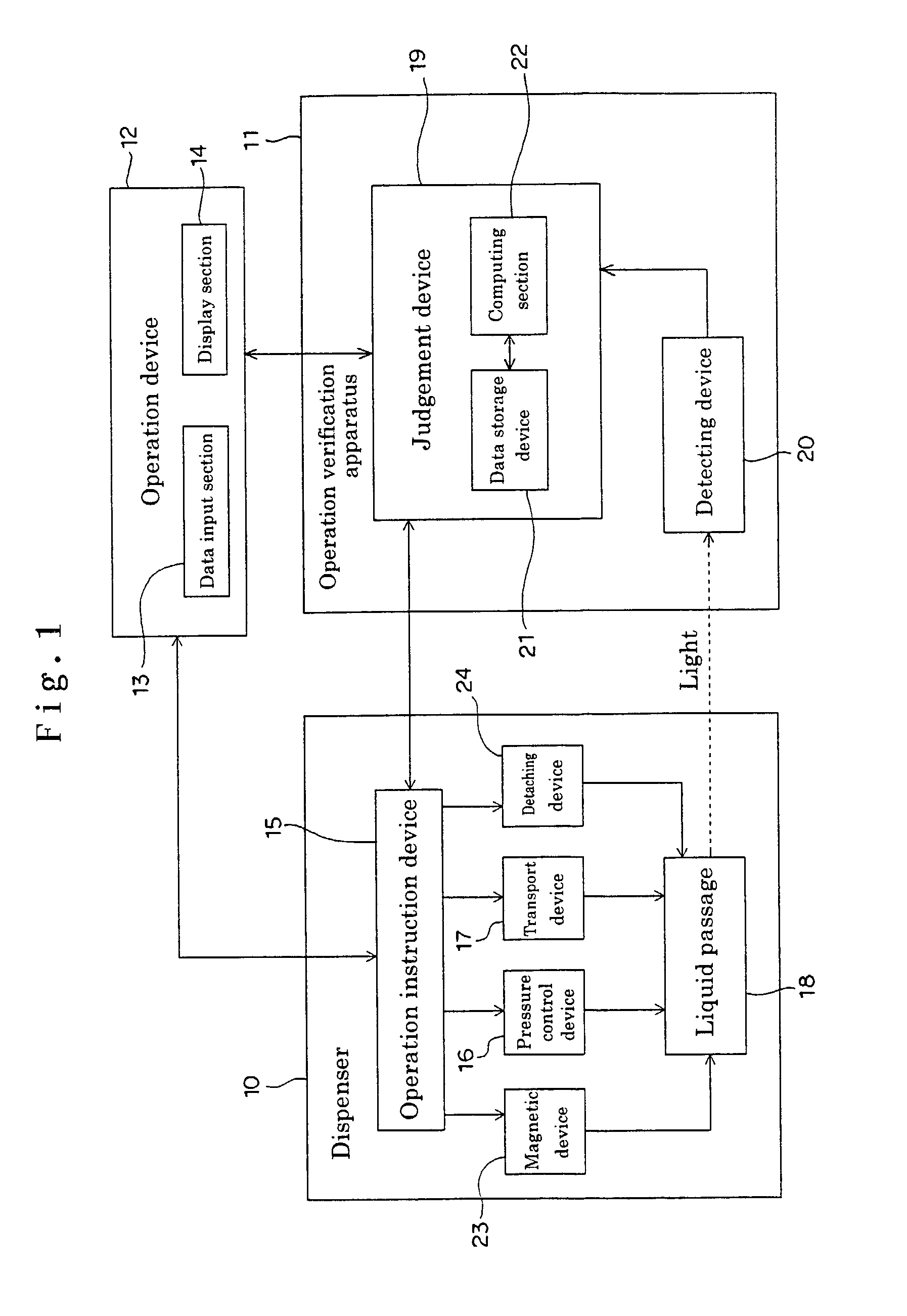
[0115]FIG. 1 shows a dispenser system 1 according to the present embodiments.
[0116]This dispenser system 1 comprises; a dispenser 10 which dispenses liquid by drawing up and discharging liquid stored in a container, an operation verification apparatus 11 for verifying the operation of the dispenser 10, and an operation device 12 for effecting input of various operation instructions and data with respect to the dispenser 10 and the operation verification apparatus 11, and also for displaying contents of operating instructions, and the result of the operation verification and the like for an operator.
[0117]Here, the operation device 12 comprises; a data input section 13 including a keyboard, switches, a mouse, a touch panel, a communication device, a CD drive, a floppy disk drive or the like for entering the operation instructions and data, and a display section 14 comprising a CRT, an LCD panel, a plasma display or the like.
[0118]The dispenser 10 comprises: one or a plurality of transparent or semi-transparent liquid passages 18 capable of liquid suction, discharge and storage; a pressure control device 16 for controlling the pressure in the liquid passage 18; a transport device 17 for performing upward and downward movement or horizontal movement of the liquid passage 18 in relation to a container; a magnetic device 23 provided outside of the liquid passage 18, capable of applying and removing a magnetic field to and from the liquid passage; a detaching device 24 for, in the case where the liquid passage 18 is constituted by a pipette tip detachably mounted on a nozzle in the dispenser 10, detaching the liquid passage 18 from the nozzle; and an operation instruction device 15 comprising: a CPU for issuing operation instructions to the pressure control device 16, the transport device 17, the magnetic device 23 and the detaching device 24. The operation instruction to be issued to the operation instruction device 15 is entered by the operator using the operation device 12.
[0119]The operation verification apparatus 11 has;: a detecting device 20 for detecting the optical condition of the liquid passage 18, a movable region thereof or a part of the region; and a judgement device 19, for judging, based on the optical condition detected by the detecting device 20, the result of the instruction related to the liquid passage 18 issued by the operation instruction device 15, and outputting the result to the display section 14 or other output device which is included in the operation device 12, for example, a printing device, a communication device, a floppy disc or the like, and optionally executing instructions for feedback to the operation instruction device 15 based on the result.
[0120]The judgement device 19 has a data storage section 21 comprising a memory device, a hard disc, an external memory device or the like, and a computing section 22 comprising a CPU, a sequencer or the like. The data storage section 21 stores, in advance or by entry from the operation device 12, information selected from amongst operation information related to the operation instruction from the operation instruction device 15, object information related to; the object that the dispenser draws in, discharges or stores, and device information related to the dispenser including the liquid passage. The computing section 22, based on the optical condition detected by the detecting device 20, the information selected from amongst the information stored in the data storage section 21, the operation information directly obtained from the operation instruction device 15, or the information input from the data input section 13, by computing, judges the condition related to the liquid passage. The computing section 22, for example, when making judgements, judges based on the object information or the device information stored in the data storage section 21 and input from the data input section 13, by comparing a standard optical condition obtained previously or by computing with the optical condition detected by the detecting device 20.
[0121]As follows is a more detailed description of each constituent.
[0122]FIG. 2 is a front view showing a dispenser 10 according to the present embodiment.
[0123]The dispenser 10 has a plurality of sets (in this example, 8) of nozzles 301–308, and a plurality of pipette tips 181 (although there are 8 sets, sets 182–188 are omitted from the figure for simplification) serving as transparent or semi-transparent liquid passages 18 attached to the lower ends of the nozzles 301–308.
[0124]In the figure, there is provided beneath the pipette tips 181, a magnetic device 23 capable of applying and removing a magnetic field to and from each of the pipette tips 181–188 when the pipette tips 181 are lowered. The magnetic device 23 has a permanent magnet 63 for applying a magnetic field to the interior of each of the pipette tips 181–188 from the outside, and a slide plate 62 capable of sliding the permanent magnet 63 backward and forward (in the figure) to approach or recede from the pipette tips 181–188. Furthermore, as shown by the hatching in the figure, a detecting device 20 of the operation verification device 11 for verify the operation of the dispenser 10, is located just above the magnetic device 23 The pipette tips 181–188 comprise: a small diameter part and a large diameter part; or a small diameter part, an intermediate diameter part and a large diameter part, and the magnetic device 21 is for applying a magnetic field to the small diameter part or the intermediate diameter part.
[0125]The nozzles 301–308 are installed in an 8-set nozzle unit 32 with an 8-set nozzle block base 31 supporting them. Each of the pipette tips 181–188, attached to the lower end of the nozzles 301–308 installed in the 8-row nozzle unit 32, is moved up and down by the transport device 17, relative to a base member 33 (column in the figure) of the dispenser 10, which supports the container, the detecting device 20 and the magnetic device 23 The transport device 17 comprises a pulley 34 driven by a stepper motor serving as a driving source (not shown in the figure), a ball screw 35 driven by a rotation force from the pulley 34, and a slide pipe 36 for guiding the upward and downward movement in the vertical direction. The 8-set nozzle unit 32 in which the nozzles 301–308 and the like are installed, is moved up and down by the rotational drive of the ball screw 35.
[0126]Furthermore, a plunger (not shown in the figure), is installed in the nozzles 301–308, so as to be slidable up and down, for the suction and discharge operations by controlling the pressure inside of the pipette tips 181–188. A stepper motor 37, serving as a drive source for driving the plunger is fixedly provided on the 8-set nozzle block base 31 by means of a supporting member 38 provided upright from the 8-set nozzle block base 31 of the 8-set nozzle unit 32. The rotating spindle of the stepper motor 37 is connected to a ball screw 40 via a coupling 39. A nut 41 is threaded onto the ball screw 40 so that the 8 set plungers is supported on a nut 41. Moreover, with the nut 41 there is provided a sliding bush 43, and the sliding bush 43, which slidingly mates with a slide pipe 42, guides the movement of the plunger up and down.
[0127]In the figure, numeral 44 denotes an origin sensor for detecting the origin of the upward and downward movement of the plunger, and numeral 45, denotes a limit sensor for the plunger operation. Both are installed on the column 33. Here, the stepper motor 37, the ball screw 40 and the like correspond to the pressure control device 16.
[0128]In the figure, numeral 46 denotes a tip off plate for detaching the pipette tips 181–188 from the nozzles 301–308, and numeral 47 denotes a tip off verification sensor for verifying the detachment of the pipette tips 181–188. These constitute the detaching device 24. Here, the whole of the dispenser 10 is stored inside of a casing provided with an opening in a lower part of a front face so that the pipette tips 181–188 can be observed from outside.
[0129]FIG. 3 shows the details of an optical sensor unit serving as the detecting device 20 according to the present embodiment. As shown in FIG. 3, the detecting device 20, which is an optical sensor, comprises light emitting elements 501–508 using LEDs, and light receiving elements 511–518 using photo diodes. These light emitting elements 501–508 and light receiving elements 511–518 are provided at a predetermined height corresponding to outside of an upward and downward movement path corresponding to a movable region of each of the pipette tips 181–188, so as to form respective pairs on either side of the path for each of the pipette tips 181–188. Here, “predetermined height” is a location through which the lower end of the pipette tips 181–188 and up to an upper level to where the liquid can be stored, can be passed through by the transport device 17.
[0130]The light emitting elements 501–508 and the light receiving elements 511–518 are fixed to a supporting member 52. Sufficient space is provided between opposite sides 52a and 52b of the supporting member 52 for the pipette tips 181–188 to pass through. Pairs of holes 54 and 53 are made, one in each side 52a and 52b along the optical axis for each transport path of the pipette tips 181–188.
[0131]Furthermore on a base 60 of the detecting device 20, as shown in FIG. 3, an amplifier 58 for amplifying the light detected by the detecting elements 511–518, a control connector 55, a power connector 56, a gain adjustment trimmer 57 and an A/D converter 59 are respectively provided.
[0132]FIG. 4(a) is an external plan view of the detecting device 20, and FIG. 4(b) is a side view of the lower part of the dispenser 10.
[0133]The slide plate 62 of the magnetic device 23 is supported and slides in a channel 64 provided on a side plate 61 made of aluminum or the like. Near a front edge of the slide plate 62, a drip receiver 65 is fitted, which is a shaped hollow or tray for receiving drips from the ends of the pipette tips 181–188. A rack 66 is provided to the rear of the slide plate 62 and meshed with a pinion 67. The pinion 67 is fixed to the same spindle as that of a belt pulley which is connected to a rotating spindle of a motor 69 via a belt 68, and thus rotated by the motor 69. Here, in the figure, numeral 70 denotes a sensor cover. In FIG. 4(a), parts covered by the sensor cover 70 are shown by perspective. Besides, numeral 71 denotes a position sensor for the slide plate 62. Numeral 72 denotes a member for supporting the side plate 61 and so on.
[0134]With the above construction, the results of the various operation instructions issued to the pressure control device 16, the transport device 17, the magnetic device 23, and the detaching device 24 are judged based on the optical condition detected by the detecting device 20. The obtained result of the judgement is, for example, displayed on the screen of the display section 14 to inform the user.
[0135]FIG. 5(a) is a plan view showing the principle outline of the detecting device 20 according to this embodiment, and FIG. 5(b) is a side view. The detecting device 20 comprises light emitting elements 501–508 and light receiving elements 511–518. The light emitting elements 501–508 and the light receiving elements 511–518 are set in opposing locations to each other along the optical axes shown by dotted lines in the figure for each of the pipette tips 181–188, outside of the upward and downward transport path of the pipette tips 181–188, with the path of the pipette tips 181–188 therebetween.
[0136]The pipette tips 181–188 (hereafter with subscripts omitted), as shown in FIG. 5(a), move upward and downward, and the light emitting elements 501–508 (hereafter with subscripts omitted) and the light receiving elements 511–518 (hereafter with subscripts omitted) are fixedly provided at a predetermined height location of the upward and downward transport path.
[0137]FIG. 6 shows the case where the detecting device 20 judges the presence of the pipette tip 18 to verify the operation.
[0138]FIG. 6(a) shows the case where the tip 18 is not attached. In this case the light from the light emitting element 50 is observed without change as light amount I0 by the light receiving element 51 as shown in the optical pattern in FIG. 6(c). In the case where the tip 18 is attached as in FIG. 6(b), the result is that the light from the light emitting element 50 is absorbed and scattered, and light amount I1 is observed by the light receiving element 50 as shown in the optical pattern in FIG. 6(c). The judgement device 19, by comparing the operation instruction and the detected optical pattern, instructs the display section 14 to display affirmative or negative.
[0139]FIG. 7 shows the case where the presence of liquid in the pipette tip 18 is judged to verify the operation.
[0140]FIG. 7(a) shows the condition when liquid is not drawn into the pipette tip 18. In this case, because the air in the tip 18 has a low refractive index, all of the light from the light emitting element 50, passing through the tip cannot be collected since the lens effect is not large, and as shown in the optical pattern in FIG. 7(c), the light amount I1 is received.
[0141]Conversely, as shown in FIG. 7(b), in the condition when liquid is drawn into the pipette tip 18, the light of the light emitting element 50 converges according to the same principle as for a cylindrical lens since there is liquid with a high refractive index in the tip 18 As a result, as shown in the optical pattern in FIG. 7(c), a far higher light amount I2 is received compared to the light amount I1 for the case with no liquid inside. Here the above description has been for the case of liquid with high light transmissivity.
[0142]On the other hand, in the case of liquid with low light transmissivity, in other words a liquid with high light absorption, most of the light passing through the tip 18 is absorbed. Therefore, as shown in the optical pattern in FIG. 7(d), for the light intensity or light amount observed, a light amount I2, which is lower than the light intensity or light amount I1 for the case where there is no liquid is observed. Accordingly, in the case where the liquid is known in advance to have low light transmissivity, the presence of the liquid can be judged by observing the low light amount.
[0143]Furthermore, liquid such as a suspension of small beads or blood serum can be reliably detected using the lens effect, by selecting visible light where the wavelength of the light of the light emitting element is 600 nm or more to prevent absorption by the liquid.
[0144]Moreover, in the case where whole blood or a suspension with an extremely high concentration of beads is used, the lens effect and light extinction by absorption counteract, which sometimes makes it difficult to detect. In this case, by dissolving a coloring matter in the solution that absorbs the wavelength of the light source being used, the light amount is decreased to less than I0, enabling accurate detection. In this way, in the case where the nature of the liquid being drawn up is known in advance, it is possible to detect accurately by the change in the observed value, that the liquid is drawn up.
[0145]FIG. 8 shows the case where the detecting device 20 judges the passing of the liquid surface in the pipette tip 18, to verify the operation.
[0146]In the case where, in the condition where the height of the tip is fixed and a high light transmissivity liquid such as a reagent or the like is drawn up, then as shown in FIG. 8(a), in the condition where the liquid surface does not go past the sensor axis, the light intensity is low, as shown in FIG. 8(c). Immediately after the liquid surface passes through, as shown in FIG. 8(b), the light intensity or the light amount increases as shown in the optical pattern in FIG. 8(c). Accordingly, if a change in the light amount is observed during the drawing up operation, it can be judged that the time of the change is the time when the liquid surface passes. On the other hand, in the case where a low light transmissivity liquid is drawn up, immediately after the liquid surface passes, the light intensity or the light amount decreases.
[0147]FIG. 9 shows the case where the liquid flow resistance or viscosity is judged, to verify the operation.
[0148]In this case, if the drawn up amount when the liquid surface in the tip 18 is on the optical axis is measured in advance, the flow resistance of the configuration can be known from a correlation of the passing through of the liquid surface and the operation position of the plunger.
[0149]In the case where the liquid is drawn up using the pressure control device 16, the timing of the passing through of the liquid surface is delayed more when drawing up a high viscosity liquid than a low viscosity liquid like water, as shown in the optical pattern in FIG. 9 (c). Also in the case of drawing up water, when the end of the tip is pressed to the bottom of the liquid container or the end of the tip is blocked with foreign matter, the timing is delayed. In the case where the tip is completely blocked, the liquid surface cannot be detected however strongly the pressure control device 16 is operated.
[0150]FIG. 10 shows the case where the detecting device 20 detects the presence of foam or flocculent or suspension in the liquid drawn into the pipette tip 18.
[0151]As shown in FIG. 10(a), in the case where a flocculent such as foam, protein or the like is mixed in a liquid such as a reagent or the like, then since as shown in the optical pattern in FIG. 10(b), the suction and discharge operation by the pressure control device 16 as well as the measurement data fluctuate greatly, the intermixing can be detected by the fluctuation value after detecting the liquid surface. Moreover, after the liquid is drawn up, by repeating the suction and discharge operation by the pressure control device 16, the fluctuation amount of the measured value can be obtained.
[0152]FIG. 11 shows the case where the detecting device 20 verifies the liquid amount drawn into the pipette tip 18.
[0153]In the condition with the liquid drawn up to below the sensor optical axis as shown in FIG. 11(a), when the pipette tip 18 is moved upward, then as shown in FIG. 11(b), at a certain time the liquid surface inside the tip 8 crosses the optical axis. As shown in the optical pattern in FIG. 11(c), by comparing the Z-axis coordinate when the sensor detects the liquid level, with translation data for the Z-axis coordinate and the liquid amount obtained in advance and stored in the data storage section 21, the liquid amount in the tip 18 can be determined.
[0154]FIG. 12 shows the case where the detecting device 20 can verify a shortage in the liquid amount of the liquid drawn into the pipette tip 18.
[0155]As shown in FIG. 12(a), in the case where the liquid drawn up is insufficient, air enters the end of the tip 18. Accordingly, in the condition where a reagent is drawn up, then as shown in FIG. 12(b), if the pipette tip 18 is moved upward along the Z axis, the two liquid surfaces are detected before reaching the end of the tip 18. That is to say, in the condition where the liquid is drawn up to the sensor optical axis or higher, if the Z axis is moved upward, then as shown in the optical pattern in FIG. 12(c), the condition changes from the condition for the presence of a reagent back to the condition for the absence of a reagent.
[0156]In the case where the liquid which the pipette tip 18 draws up according to the embodiment is semi-transparent with respect to the observing light source, this is also applicable. In the case of a semi-transparent liquid, depending on the light transmissivity, light convergence by the lens effect and light extinction by absorption and scattering counteract so that there is a possibility of difficulty in clearly distinguishing the light amount of the tip 18 itself. In this case, by mixing in advance in the liquid to be drawn up, coloring matter that has sufficient absorption for the wavelength to be observed, enables an accurate distinction
[0157]Each of the above-described embodiments is described specifically for the purpose of better understanding the present invention, and does not exclude other embodiments. Accordingly, modification is possible within the scope in which the gist of the invention is not changed. For example, in the above explanation, the nozzle and pipette tip are movable up and down by the transport device, and the detecting device is described for the case where the light emitting element and light receiving element are fixed. However, the nozzle and the pipette tip may be movable horizontally as well, and it is also possible for the nozzle and the pipette tip to be fixed and for only the container to move. In that case, the light emitting element and the light receiving element of the detecting device would be movable. Furthermore, the light that the light emitting element emits is described for the case of visible light, however, it is not restricted to the case of visible light, and infrared light, ultraviolet light or the like can be used. Moreover, by fitting a filter in front of the light emitting device, it is possible to emit various wavelengths of light.
[0158]Furthermore, according to the above explanation, the light emitting device and the light receiving device are used as the detecting device, however, it is possible to use an image pick-up device. Moreover, in the above explanation, the verification of the operation by the magnetic device is not explained, however, it is possible to verify the result of applying and removing a magnetic field by the magnetic device. The above example is described for the case where a pipette tip is detachably mounted on a nozzle, however, it is possible that the nozzle itself is a transparent or semi-transparent liquid passage without a pipette tip.
[0159]According to the above explanation, the judgement result is described only in the case of displaying this on the display section to inform the operator, however, it is possible to inform by other means such as an alarm sound, voice or the like. Furthermore, it is possible, based on the judgement result obtained, to use feedback to control the operation, by sending a signal to the operation instruction device 15.
[0160]Moreover, in the above explanation, the light emitting device of the detecting device is limited to one kind, however, it is possible to emit light by selecting from a plurality of light emitting device depending on the object of the verification such as the liquid type or the like, by instructions from the operation section, or to insert and remove a plurality of filters between the light emitting device and the liquid passage. Furthermore, in the above explanation, as the magnetic device, a magnet provided so as to be able to approach and recede from the pipette tip is used, however, it is possible to use a means whereby turning an electromagnet on or off applies and removes a magnetic field to and from inside the liquid passage. Moreover, the invention is not limited to the 8-set nozzles, and by providing two or more of the light receiving device or image pick-up device, it is also applicable to a dispenser in which the nozzles are arrayed in matrix form.

PUM

no PUM

Description & Claims & Application Information

We can also present the details of the Description, Claims and Application information to help users get a comprehensive understanding of the technical details of the patent, such as background art, summary of invention, brief description of drawings, description of embodiments, and other original content. On the other hand, users can also determine the specific scope of protection of the technology through the list of claims; as well as understand the changes in the life cycle of the technology with the presentation of the patent timeline. Login to view more.
Why Eureka
Try Eureka