
Spin tunnel magnetoresistive effect film and element, magnetoresistive sensor using same, magnetic apparatus, and method for manufacturing same

a technology of magnetoresistive effect and spin tunnel, applied in the direction of nanoinformatics, magnetic bodies, instruments, etc., can solve the problem of reducing the effectiveness of the lower layer, and achieve the effect of suppressing oxidation

Inactive Publication Date: 2007-01-09
NEC CORP
View PDF7 Cites 15 Cited by
  • Summary
  • Abstract
  • Description
  • Claims
  • Application Information

AI Technical Summary

Benefits of technology

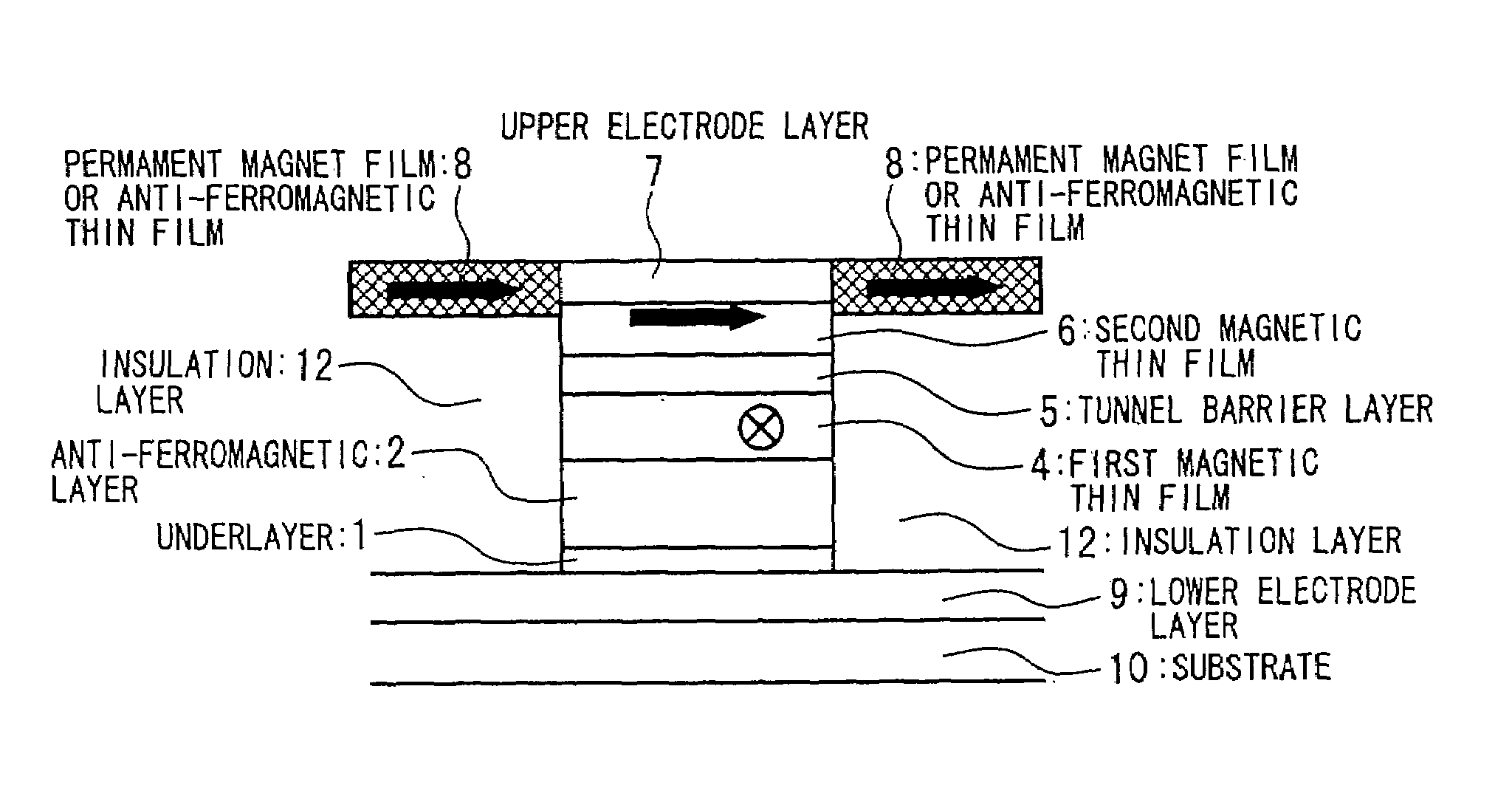
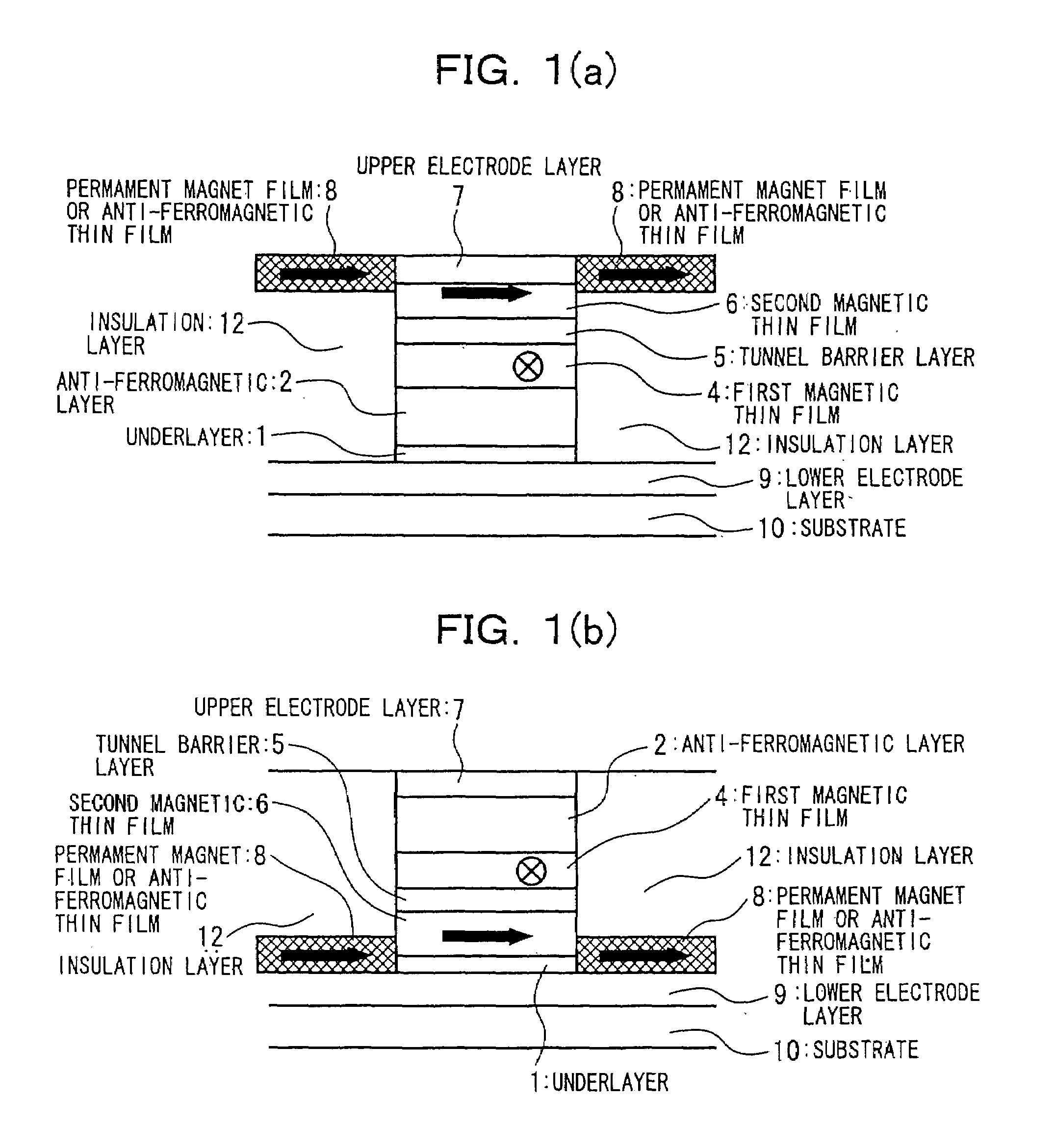
[0023]The lower layer exhibits flatness in the spin tunnel magnetoresistive effect film and a clear boundary in the multilayer films, and it is desirable that this be Ta, Hf, Zr, or an alloy thereof. In the case in which Ta, Hf, Zr, or an alloy thereof is used as the lower layer, it is desirable that the film thickness be from 10 to 100 Angstroms. This is because with a film thickness of less than 10 Angstroms there is a loss of effect as a lower layer, and with a film thickness of greater than 100 Angstroms the lower layer changes from the amorphous state to the crystalline state, thereby reducing its effectiveness as a lower layer.
[0048]In a spin tunnel magnetoresistive effect film according to the present invention, it is possible to laminate Ta, Hf, Zr, or Ti or the like onto the uppermost layer as a protective film to suppress oxidation.

Problems solved by technology

This is because with a film thickness of less than 10 Angstroms there is a loss of effect as a lower layer, and with a film thickness of greater than 100 Angstroms the lower layer changes from the amorphous state to the crystalline state, thereby reducing its effectiveness as a lower layer.

Method used


Image

  • Spin tunnel magnetoresistive effect film and element, magnetoresistive sensor using same, magnetic apparatus, and method for manufacturing same
  • Spin tunnel magnetoresistive effect film and element, magnetoresistive sensor using same, magnetic apparatus, and method for manufacturing same
  • Spin tunnel magnetoresistive effect film and element, magnetoresistive sensor using same, magnetic apparatus, and method for manufacturing same

Examples


Embodiment Construction

[0069]Embodiments of the present invention are described in detail below, with reference made to relevant accompanying drawings.

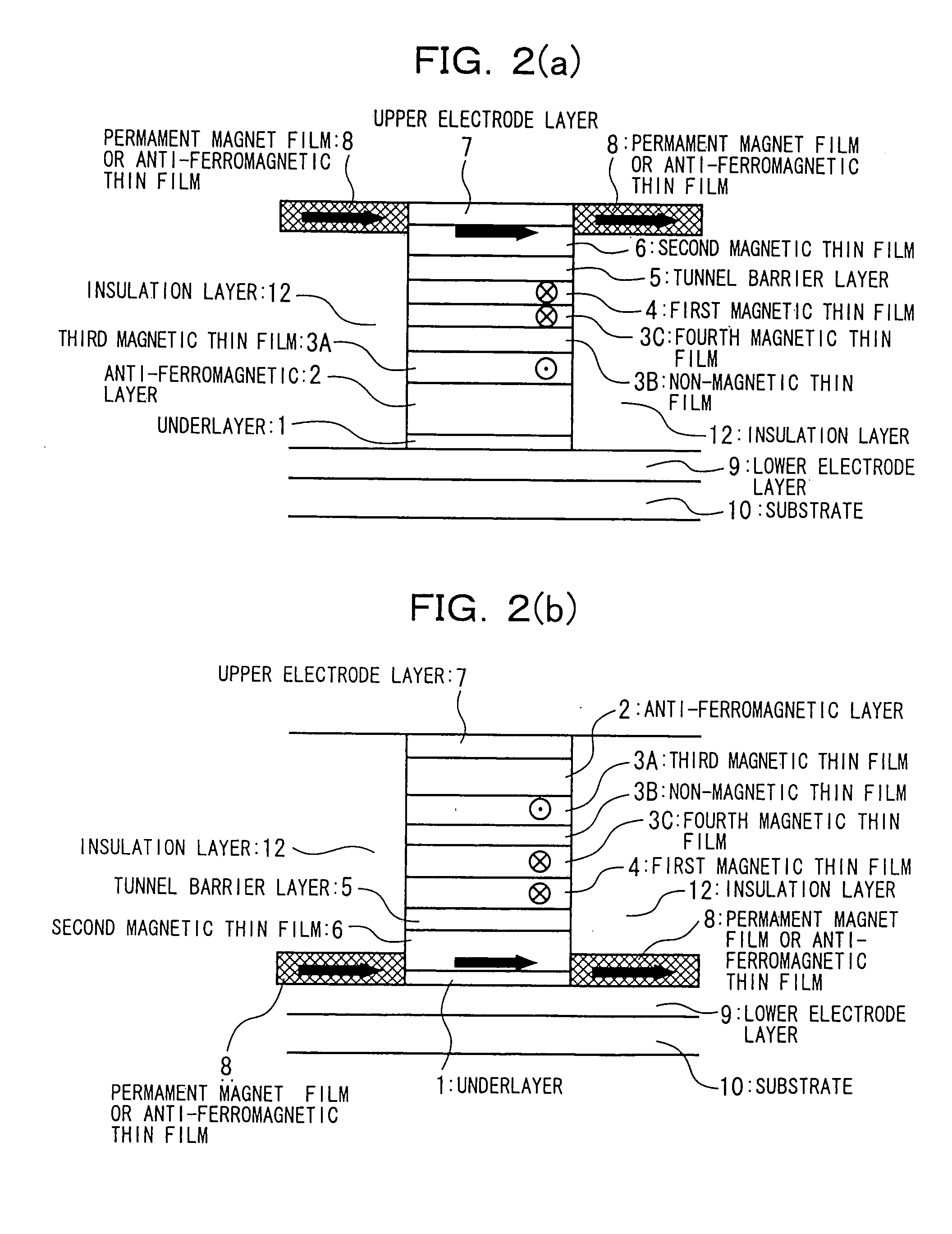
[0070]In a spin tunnel magnetoresistive effect element according to the present invention an anti-ferromagnetic thin film is formed adjacent (or adjacent to via an intervening anti-ferromagnetically coupled three-layer film therebetween) to one of the magnetic thin films, and it is necessary that an exchange bias be operative.

[0071]The reason for this is that the principle of the present invention is one in which, when the magnetization orientations of neighboring magnetic thin films are mutually opposite, the maximum resistance is exhibited. Thus, in the present invention, as shown in FIG. 4(a) when an external magnetic field H is between the anisotropic magnetic field Hk2 of the magnetic thin film and the coercivity Hr of one of the magnetic thin films, that is, when Hk2


PUM

PropertyMeasurementUnit
pressureaaaaaaaaaa
surface roughnessaaaaaaaaaa
pressureaaaaaaaaaa

Abstract

In a spin tunnel magnetoresistive effect film in which a magnetic thin film to which an exchange bias is applied by exchange coupling via an anti-ferromagnetic thin film and a magnetic thin film that detects a magnetic field are laminated, a magnetic thin film or an anti-ferromagnetic thin film (PtMn, PdMn, NiMn) is laminated onto an underlayer (Ta, Zr, Hf), the surface roughness thereof being in the range from 0.1 to 5 Angstroms. A means used to control the surface roughness introduces into the film growing chamber oxygen, nitrogen, hydrogen, or a gas mixture thereof into a vacuum of 10−6 Torr to 10−9 Torr, reduces the substrate temperature to 0° C. or lower during film growth, or oxidizes an underlayer. The lower electrode layer material used is a film laminate of a high-permeability amorphous magnetic material and a non-magnetic metallic layer.

Description

CROSS REFERENCE TO RELATED APPLICATIONS[0001]This application is a divisional of U.S. patent application Ser. No. 10 / 033,669 filed on Dec. 28, 2001 (now abandoned).BACKGROUND OF THE INVENTION[0002]1. Field of the Invention[0003]The present invention relates to a spin tunnel magnetoresistive effect element for reading a magnetic field strength, which is information recorded on a magnetic medium or the like, as a signal, and to a spin tunnel magnetoresistive effect film used therein, and more particularly it relates to a spin tunnel magnetoresistive effect film, a spin tunnel magnetoresistive effect element, and a spin tunnel magnetoresistive effect sensor and magnetic apparatus using the element, that achieve a large output with a small external magnetic field.[0004]2. Related Art[0005]A ferromagnetic tunnel junction has a construction in which a tunnel barrier layer made of an insulation film having a thickness of several nanometers is sandwiched between two ferromagnetic layers. In...

Claims


Application Information

Patent Timeline
Patent Type & Authority Patents(United States)
IPC IPC(8): B05D5/12G01R33/09G11B5/00G11B5/39H01F10/16H01F10/32H01L43/08H01L43/12
CPCB82Y10/00B82Y25/00G11B5/3903H01F10/3268H01L43/08H01L43/12G11B5/3909G11B5/00Y10T428/1114H10N50/01H10N50/10G11B5/39G01R33/09
Inventor FUJIKATA, JUNICHIISHI, TSUTOMUMORI, SHIGERU
Owner NEC CORP
Learn More