
Hologram element

a hologram element and hologram technology, applied in the field of hologram elements, can solve the problems of inability to detect pit data properly, failure of optical pickup apparatus, and difficulty in properly controlling the depth and opening width of the groove of the diffraction grating, so as to achieve the effect of optimum optical characteristics and equal first-order diffraction efficiency

Active Publication Date: 2007-01-09
SHARP KK
View PDF6 Cites 3 Cited by
  • Summary
  • Abstract
  • Description
  • Claims
  • Application Information

AI Technical Summary

Benefits of technology

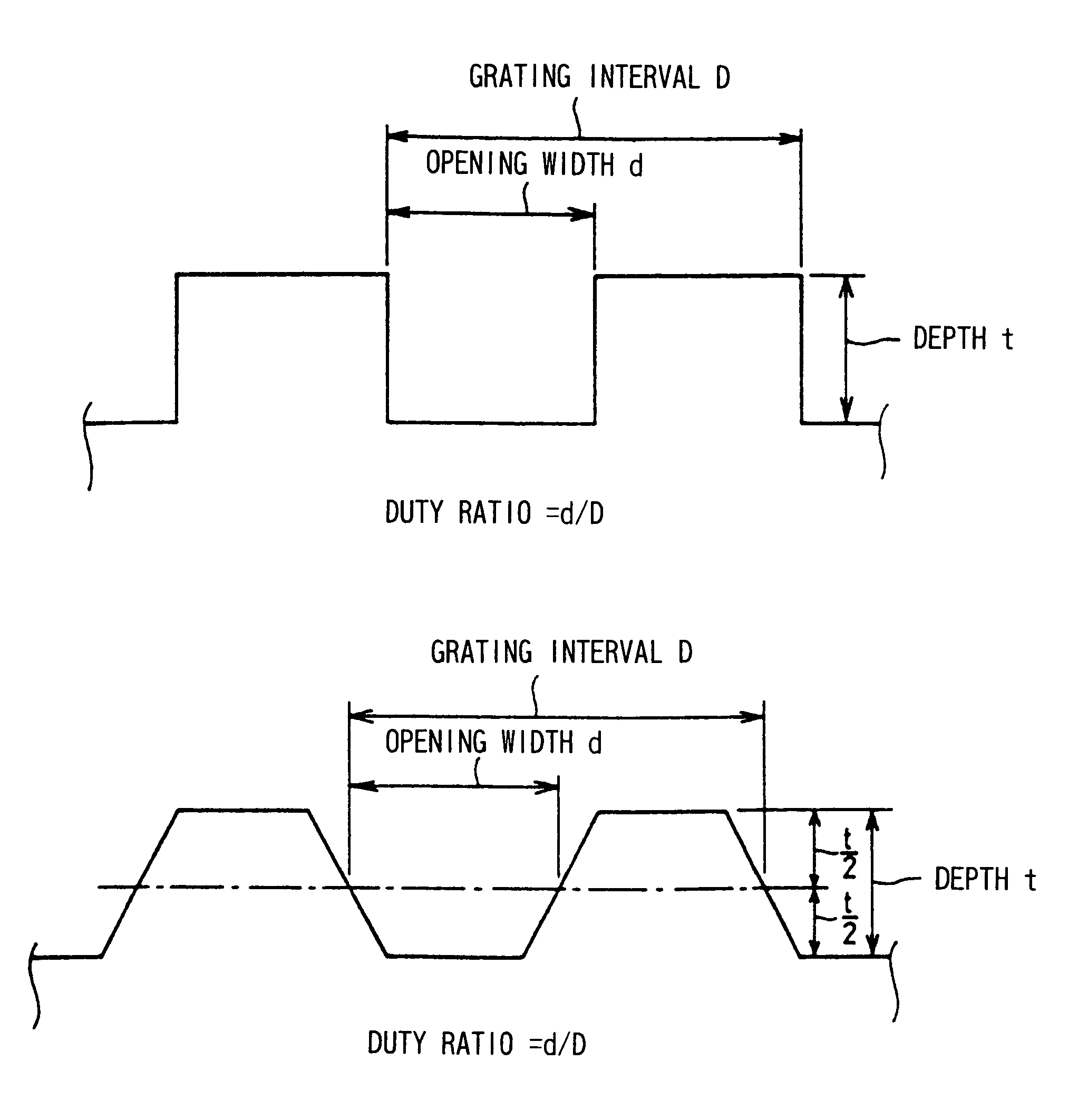
[0035]Even if, in the hologram element, the hologram regions have different diffraction grating intervals, as long as the diffraction gratings of the regions have equal duty ratio, a certain exposure-amount value at which the regions are equal in first-order diffraction efficiency generally signifies a certain exposure-amount value at which the regions each have the maximum first-order diffraction efficiency. Moreover, it has been known that, the smaller the duty ratio of the diffraction grating in the hologram, the larger the exposure-amount value corresponding to the maximum first-order diffraction efficiency. Further, a graph showing the relationship between light exposure amounts in the production of the diffraction grating of each hologram region and the first-order diffraction efficiency commonly takes on a convex form wherein the first-order diffraction efficiency is at the maximum when the light exposure amount reaches a certain level. In the graph, the greater the grating interval, the gentler the curve can be with respect to the vertex indicating the exposure amount corresponding to the maximum first-order diffraction efficiency. Thus, in the hologram element, by adjusting the duty ratio of the diffraction grating having a shorter grating interval to be smaller than that of the diffraction grating having a longer grating interval, it is possible to make the exposure amount corresponding to the maximum first-order diffraction efficiency larger in the region having a diffraction grating with a shorter grating interval than in the region having a diffraction grating with a longer grating interval. Moreover, a desired value can be assigned to the exposure amount with which the hologram regions are equal in first-order diffraction efficiency. In this way, a desired value can be assigned to the exposure amount with which the hologram regions are equal in first-order diffraction efficiency, in other words, the first-order diffraction efficiency ratio between the regions is given as 1.0. Therefore, during the photolithography-based exposure process, the photoresist can be prevented from undergoing insufficient light exposure caused by the exposure amount being smaller than the desired value. Further, a hologram element exhibiting desired optical characteristics can be realized without fail.
[0054]According to the invention, the hologram element includes the hologram divided into a plurality of regions in each of which a diffraction grating is formed. Of the regions, at least two regions differ in diffraction grating interval, but are equal in first-order diffraction efficiency. In the hologram element thus constructed, since at least two hologram regions have different diffraction grating intervals, a difference is caused between the regions in relationship between light exposure amounts in the formation of the diffraction gratings of the regions and the first-order diffraction efficiency. Moreover, since the regions are equal in first-order diffraction efficiency, the first-order diffraction efficiency ratio between the regions is given as 1.0. Thus, the hologram element succeeds in providing optimum optical characteristics.

Problems solved by technology

However, with recent improvements in the technology on disc drives and light detecting portions including light-receiving elements, it has become possible to obtain satisfactory reproduction characteristics even though signal light is not sufficiently intense.
In this case, if the diffraction gratings of the respective hologram regions are unequal in first-order diffraction efficiency (i.e. the ratio of the first-order diffracted light quantity to the whole light quantity), an offset is caused in the tracking error signal, and thus the optical pickup apparatus fails to achieve the following of the track on the optical disc by a light beam.
As a result, the pit data cannot be detected properly.
However, it is difficult to properly control the groove depth and groove opening width of the diffraction grating.
When the light exposure amount is at a level other than the aforementioned level, the region having a shorter grating interval has lower first-order diffraction efficiency.
However, such a vapor-depositing process adversely affects the ideal steric structure of the diffraction grating fabricated by means of photolithography, resulting in a decrease in the first-order diffraction efficiency of the first and second regions.

Method used


Image

  • Hologram element
  • Hologram element
  • Hologram element

Examples


Embodiment Construction

[0083]Now referring to the drawings, preferred embodiments of the invention are described below.

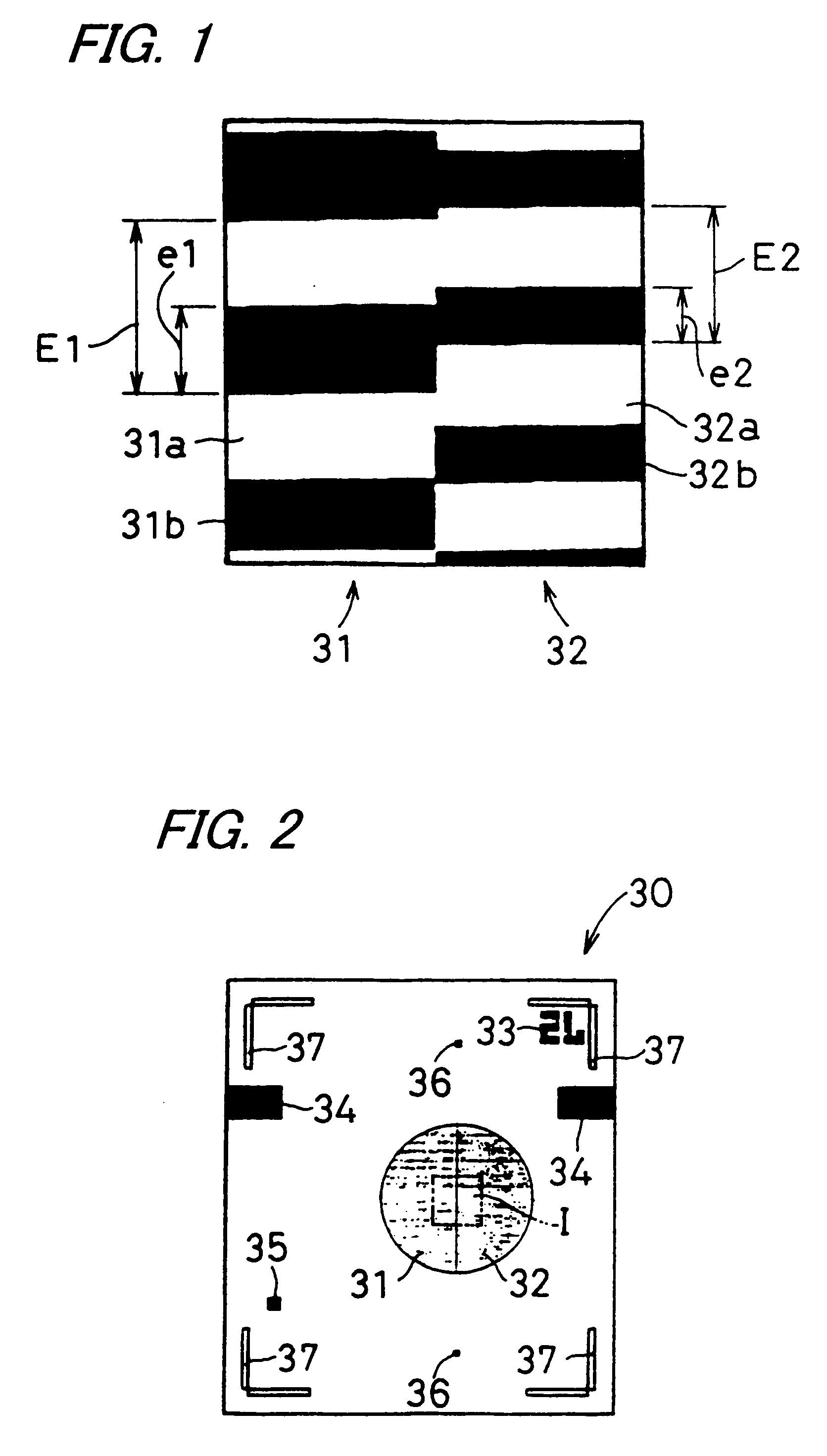
[0084]FIG. 1 is a plan view of a first photomask 30 according to one embodiment of the invention, illustrating a first mask region 31 and a second mask region 32 in an enlarged state. FIG. 2 is a plan view showing the first photomask 30 as a whole. FIG. 1 is an enlarged view showing Section I in the vicinity of the boundary between the first and second mask regions 31 and 32 shown in FIG. 2. The first photomask 30 is designed for use in the photolithography-based production of an a-model hologram element having a hologram which is divided into a plurality of regions, in this embodiment, two regions: a first region and a second region, in each of which a diffraction grating is formed.

[0085]The first photomask 30 includes a plurality of mask regions, in this embodiment, two mask regions: the first mask region 31 and the second mask region 32, for forming the diffraction gratings of the firs...


PUM


Abstract

Provided in a photomask for use in production of a hologram element having desired optical characteristics, a method for producing a hologram element, and a hologram element having desired optical characteristics. The first photomask is used for photolithography-based production of a hologram element having a hologram divided into two regions carrying a diffraction grating. The first photomask includes the first, second mask region having the non-light-transmitting mask portion and the light-transmitting portion, for forming the diffraction gratings of the regions of the hologram. The two mask regions differ in alignment-direction-wise arrangement interval for the light-transmitting portions and in ratio of the alignment-direction-wise width to the alignment-direction-wise arrangement interval for the light-transmitting portions.

Description

BACKGROUND OF THE INVENTION[0001]1. Field of the Invention[0002]The present invention relates to a photomask used for production of a hologram element designed for use in an optical pickup device which is mounted in an optical disk recording / reproducing apparatus, a method for producing a hologram element using a photomask, and a hologram element.[0003]2. Description of the Related Art[0004]An optical disc such as compact disc (abbreviated as CD) or digital versatile disc (abbreviated as DVD) is capable of recording large volumes of information at high recording density, and thus finds a wider range of applications. For example, it is employed in an audiovisual system and a computer.[0005]FIG. 15 is a perspective view showing an optical pickup apparatus 1 of conventional design. The optical pickup apparatus 1 is composed of a photodetector 2, a beam splitter 3, a collimator lens 4, an objective lens 5, and a light source 6. Light emitted from the light source 6 is reflected from the...

Claims


Application Information

Patent Timeline
IPC IPC(8): G01F9/00G03H1/04G02B5/18G02B5/32G03F1/00G03F1/70G03F7/20G03H1/02G11B7/135G11B7/1353
CPCG02B5/32G11B7/1353G03H1/02G03H2260/14
Inventor KUMAGAI, MUNESATO
Owner SHARP KK
Learn More