Carbon nanotube array and method for making same

a technology of carbon nanotubes and arrays, applied in the direction of discharge tubes/lamp details, metal/metal-oxide/metal-hydroxide catalysts, etc., can solve the problem of limiting the diversified design of carbon nanotube-based structures, difficult to realize localized and versatile direction control by any external field, and inability to properly control the direction in which aligned nanotubes extend

Active Publication Date: 2007-01-09
TSINGHUA UNIV +1
View PDF2 Cites 20 Cited by
  • Summary
  • Abstract
  • Description
  • Claims
  • Application Information

AI Technical Summary

Benefits of technology

[0015]FIG. 1 is a schematic side elevation view of a substrate with a catalyst layer deposited thereon, in accordance with a preferred method of the present invention for making a carbon nanotube-based device;
[0013]In order to achieve the objects set out above, the present invention provides a method for making a carbon nanotube-based device. The method is able to control a direction of growth of a carbon nanotube array, and comprises the steps of: (1) providing a substrate; (2) depositing a layer of catalyst on the substrate; (3) depositing a layer of catalyst dopant material on the catalyst layer, for varying a reaction rate of synthesis of an aligned carbon nanotube array; (4) annealing the catalyst and the catalyst dopant material in an oxygen-containing gas at a low temperature; and (5) exposing the nano-sized particles and catalyst dopant material to a carbon-containing source gas at a predetermined temperature such that the aligned carbon nanotube array grows from the substrate.

Problems solved by technology

However, synthesis of large amounts of carbon nanotubes having practical applications depends in large part on manufacturing techniques developed using a bottom-up approach.
However, in all the above-mentioned methods, it is not possible to properly control a direction in which the aligned nanotubes extend.
It is difficult to realize localized and versatile direction control by any external field like an electric field.
This limits the diversified design of carbon nanotube-based structures.

Method used


Image

  • Carbon nanotube array and method for making same
  • Carbon nanotube array and method for making same

Examples


Embodiment Construction

[0019]Reference will now be made to the drawings to describe the present invention in detail.

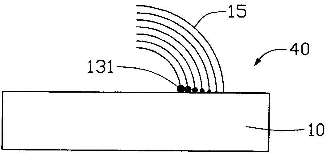
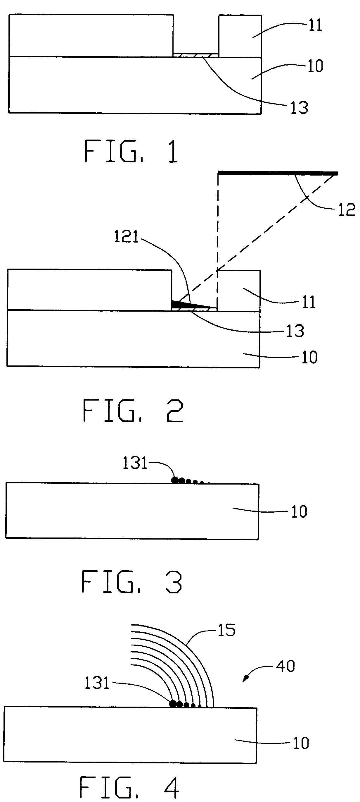
[0020]Referring to FIG. 4, a carbon nanotube-based device 40 in accordance with a preferred embodiment of the present invention comprises a substrate 10, a plurality of alloy catalytic nano-sized particles 131 formed on the substrate 10, and an aligned carbon nanotube array 15 extending from the alloy catalytic nano-sized particles 131. The aligned carbon nanotube array 15 progressively bends in a predetermined direction.

[0021]Referring to FIGS. 1–4, a preferred method of the present invention for making the carbon nanotube-based device 40 is as follows:

[0022]First, a substrate 10 is provided, which may be selected from the group consisting of silicon, quartz and glass. A photo-resist layer 11 is formed on the substrate 10. A catalyst layer 13 is deposited on the substrate 10 by electron-beam (e-beam) evaporation or thermal evaporation. The catalyst layer 13 must have a uniform thickness, pr...


PUM

PropertyMeasurementUnit
length/diameteraaaaaaaaaa
thicknessaaaaaaaaaa
thicknessaaaaaaaaaa

Abstract

A carbon nanotube-based device (40) includes a substrate (10), a number of catalytic nano-sized particles (131) formed on the substrate, and an aligned carbon nanotube array (15) extending from the alloy catalytic nano-sized particles. The aligned carbon nanotube array progressively bends in a predetermined direction. A method for making the carbon nanotube-based device includes the steps of: providing a substrate; depositing a layer of catalyst on the substrate; depositing a layer of catalyst dopant material on the catalyst layer, for varying a reaction rate of synthesis of the aligned carbon nanotube array; annealing the catalyst and the catalyst dopant material in an oxygen-containing gas at a low temperature; and exposing the nano-sized particles and catalyst dopant material to a carbon-containing source gas at a predetermined temperature such that the aligned carbon nanotube array grows from the substrate.

Description

BACKGROUND OF THE INVENTION[0001]1. Field of the Invention[0002]The present invention relates to carbon nanotube-based devices and methods for making such devices. The application relates to a contemporaneously filed application titled “CARBON NANOTUBE-BASED DEVICE AND METHOD FOR MAKING THE SAME” and having the same applicants and the same assignee with the instant application.[0003]2. Description of Related Art[0004]Carbon nanotubes have electrical conductance relate to their structure and chemically stable. Carbon nanotubes typically have very small diameters (less than 100 nanometers) and large aspect ratios (length / diameter). Due to these and other properties, it has been suggested that carbon nanotubes will play an important role in fields such as nano-scale integrate circuits, field emission, and single electronic components such as single electronic transistors. Recently, some electronic components based on a single carbon nanotube have been made in laboratories, such compone...

Claims


Application Information

Patent Timeline
Patent Type & Authority Patents(United States)
IPC IPC(8): H01J1/05D01F9/12B82B1/00B01J23/745B82B3/00C01B31/02C23C14/16C23C16/26D01F9/127H01L29/06
CPCB82Y30/00D01F9/127D01F9/1275Y10S977/85Y10S977/742
Inventor LIU, LIANGFAN, SHOU-SHAN
Owner TSINGHUA UNIV
Why Eureka
Try Eureka