
2-D projectile trajectory correction system and method

Active Publication Date: 2007-01-16
RAYTHEON CO
View PDF47 Cites 66 Cited by
  • Summary
  • Abstract
  • Description
  • Claims
  • Application Information

AI Technical Summary

Benefits of technology

[0013]The present invention provides a 2-D correction system for accurately correcting both the range and deflection errors inherent in an unguided spin or fin stabilized projectile that can be used with existing ballistic firing tables and retrofitted to existing projectiles.

Problems solved by technology

Unguided artillery shells follow a ballistic trajectory, which is generally predictable but practically results in larger misses at ranges greater than 20 miles due to variations in atmospheric conditions; wind speed and direction, temperature and precipitation, and variations in the weapons system; manufacturing tolerances, barrel condition, propellant charge temperature and gun laying errors.
As the ballistic range increases, the potential impact of the projectile variation grows until the projectile delivered lethality is too low to effectively execute the fire mission.
Precision in such weapons comes at a high cost.
Such high cost systems are not feasible to modify the millions of artillery rounds in the existing inventory or to be integrated into the design of new artillery rounds.
If atmospheric conditions change, the brake cannot adjust.
The brake is easy to implement but also suffers in that cross range errors (˜100 m DEP) are not reduced.
If atmospheric conditions change, the system cannot adjust.
A one-time deployment of a fin or canard is easily implemented but suffers in that down range errors (>100 m REP) are not reduced.
If atmospheric conditions change after deployment, the system cannot adjust.
This is an easily implementable system but suffers in that it requires a substantial change to the ballistic firing tables to be used operationally.
These systems suffer in that the de-coupling mechanism is bulky and the fuze outer mold line cannot follow the NATO STANAG shapes such that new and different ballistic firing tables are required to be used operationally.

Method used


Image

  • 2-D projectile trajectory correction system and method
  • 2-D projectile trajectory correction system and method
  • 2-D projectile trajectory correction system and method

Examples


Embodiment Construction

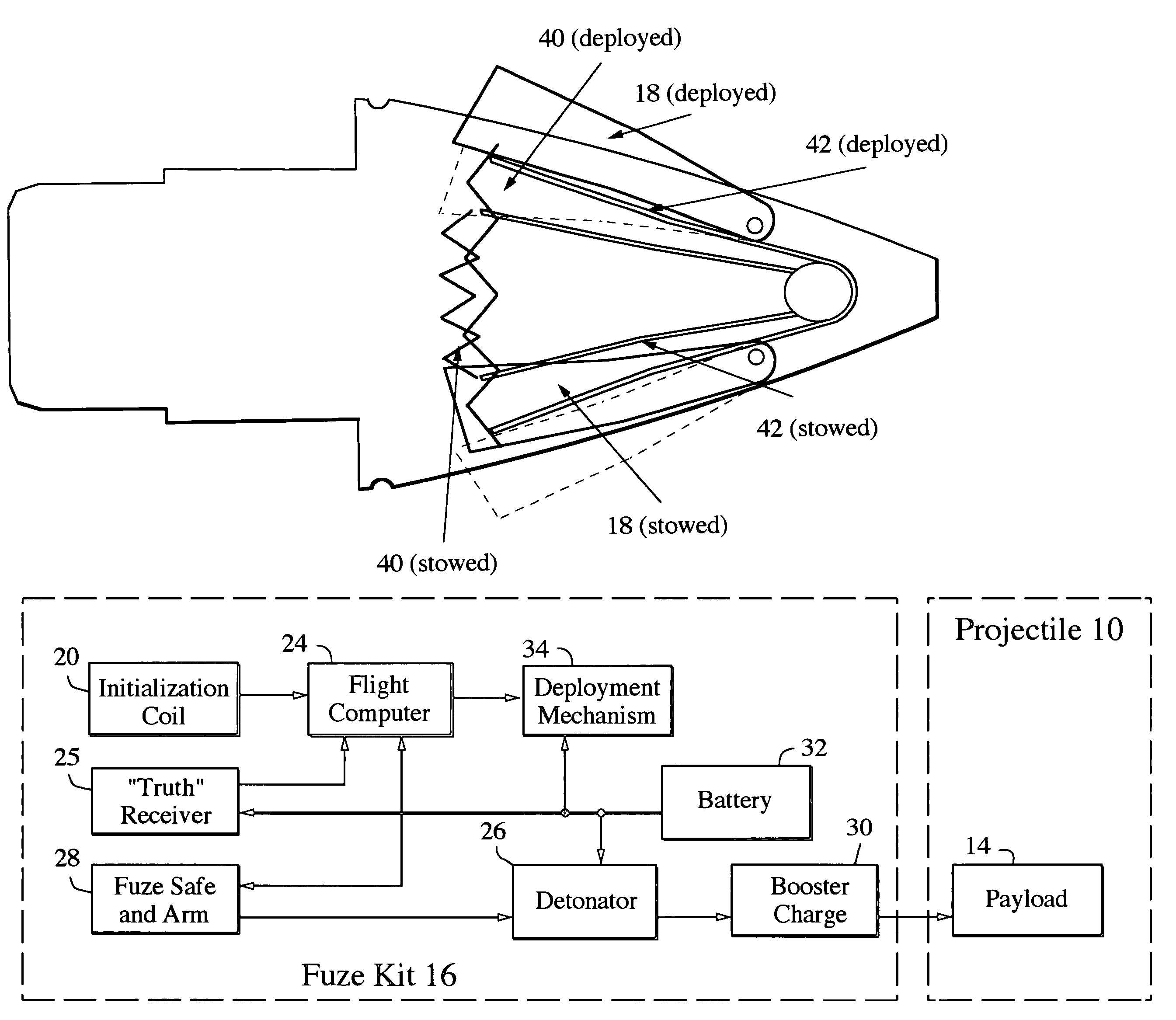
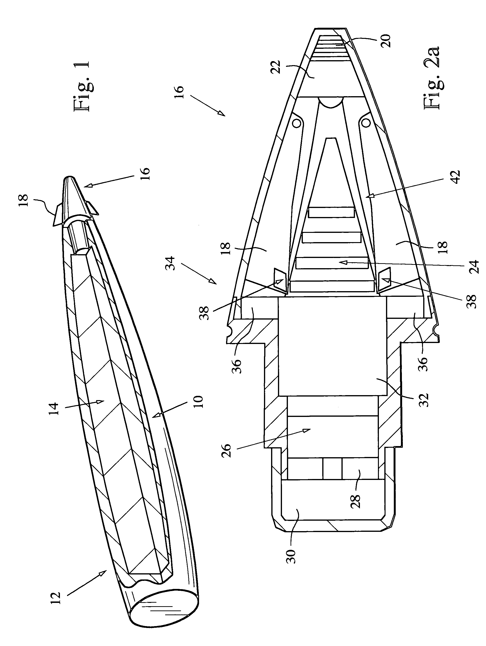
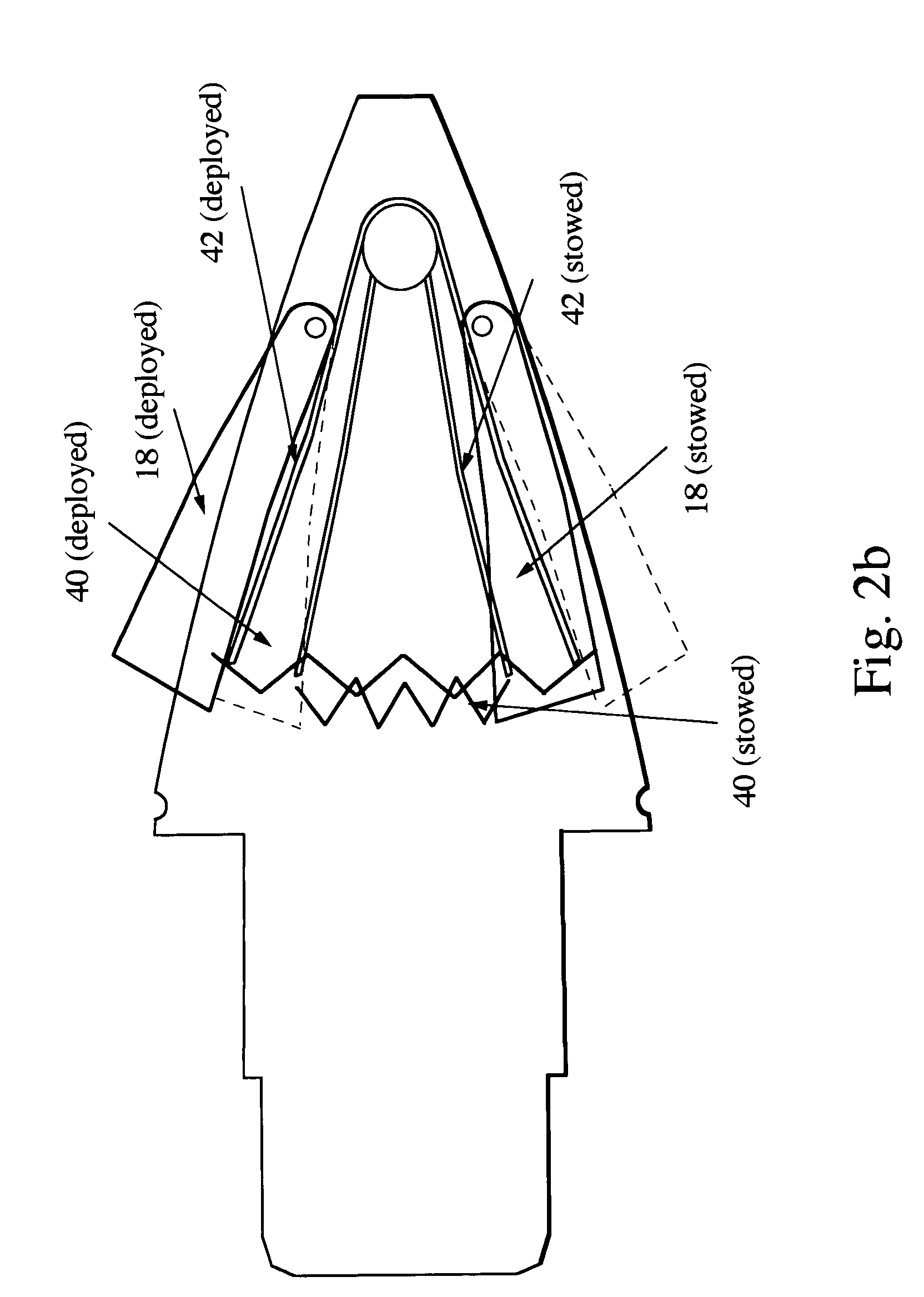
[0028]The present invention provides a 2-D correction system for accurately correcting both the range and deflection errors inherent in an unguided spin or fin stabilized projectile (artillery shells, missiles, EKVs) that can be used with existing ballistic firing tables and retrofitted to existing projectiles. This is accomplished by intermittently deploying aerodynamic surfaces to develop a rotational moment, which creates body lift that nudges the projectile in two-dimensions to return the projectile to its ballistic trajectory. In spin stabilized projectiles, the rotational moment causes a much larger orthogonal precession, which in turn moves the projectile. The aerodynamic surfaces are suitably deployed over multiple partial roll cycles at precise on (deployed) and off (stowed) positions in the cycle to nudge the projectile up or down range or left or right cross range until the desired ballistic trajectory is restored.

[0029]As shown in FIG. 1, an unguided spin stabilized proj...


PUM


Abstract

A 2-D correction system uses intermittent deployment of aerodynamic surfaces to control a spin or fin stabilized projectile in flight; correcting both crossrange and downrange impact errors. Intermittent surface deployment develops rotational moments, which create body lift that nudge the projectile in two-dimensions to correct the projectile in its ballistic trajectory. In low spin rate projectiles (“fin stabilized”), the rotational moment directly produces the body lift that moves the projectile. In high spin rate projectiles (“spin stabilized”), the rotational moment creates a much larger orthogonal precession that in turn produces the body lift that moves the projectile. The aerodynamic surfaces are suitably deployed over multiple partial roll cycles at precise on (deployed) and off (stowed) positions in the cycle to nudge the projectile up or down range or left or right cross range until the desired ballistic trajectory is restored.

Description

BACKGROUND OF THE INVENTION[0001]1. Field of the Invention[0002]This invention relates to launched projectiles in general, and specifically to a two-dimensional correction system and method for correcting the range and deflection errors in an unguided spin or fin stabilized projectile.[0003]2. Description of the Related Art[0004]Modern warfare is based on mission speed, high per round lethality, and low possibility of collateral damage. This requires high precision. Unguided artillery shells follow a ballistic trajectory, which is generally predictable but practically results in larger misses at ranges greater than 20 miles due to variations in atmospheric conditions; wind speed and direction, temperature and precipitation, and variations in the weapons system; manufacturing tolerances, barrel condition, propellant charge temperature and gun laying errors. As the ballistic range increases, the potential impact of the projectile variation grows until the projectile delivered lethalit...

Claims


Application Information

Patent Timeline
IPC IPC(8): F42B10/32
CPCF42B10/64B64C9/36
Inventor GESWENDER, CHRIS E.HINSDALE, ANDREW J.BLAHA, GEORGE A.DRYER, RICHARD
Owner RAYTHEON CO
Learn More