In-head converter with display

a technology of in-head converters and displays, which is applied in the direction of heat measurement, coupling device connections, instruments, etc., can solve the problems of requiring separate circuitry for each unit, affecting the quality of the conversion circuit, and being as expensive as the conversion circuit. , to achieve the effect of convenient replacement and/or upgrading, low manufacturing cost and short tim

Inactive Publication Date: 2007-01-16
ZACAY ELY
View PDF6 Cites 17 Cited by
  • Summary
  • Abstract
  • Description
  • Claims
  • Application Information

AI Technical Summary

Benefits of technology

[0011]Typical and generally desirable results are that the circuit and display as a unit are cheaper to manufacture (fewer components), that there are no open plugs in the probe that may serve as the starting point of moisture penetration or corrosion and/or that a damaged circuit can easily be replaced and/or upgraded, in a short time. Optionally, the connection head is made transparent, so that the display may be viewed while the case is closed.
[0012]In an exemplar

Problems solved by technology

Periodic testing of all the conversion circuits in a factory is thus often a particular laborious activity.
Bein

Method used


Image

  • In-head converter with display
  • In-head converter with display
  • In-head converter with display

Examples


Embodiment Construction

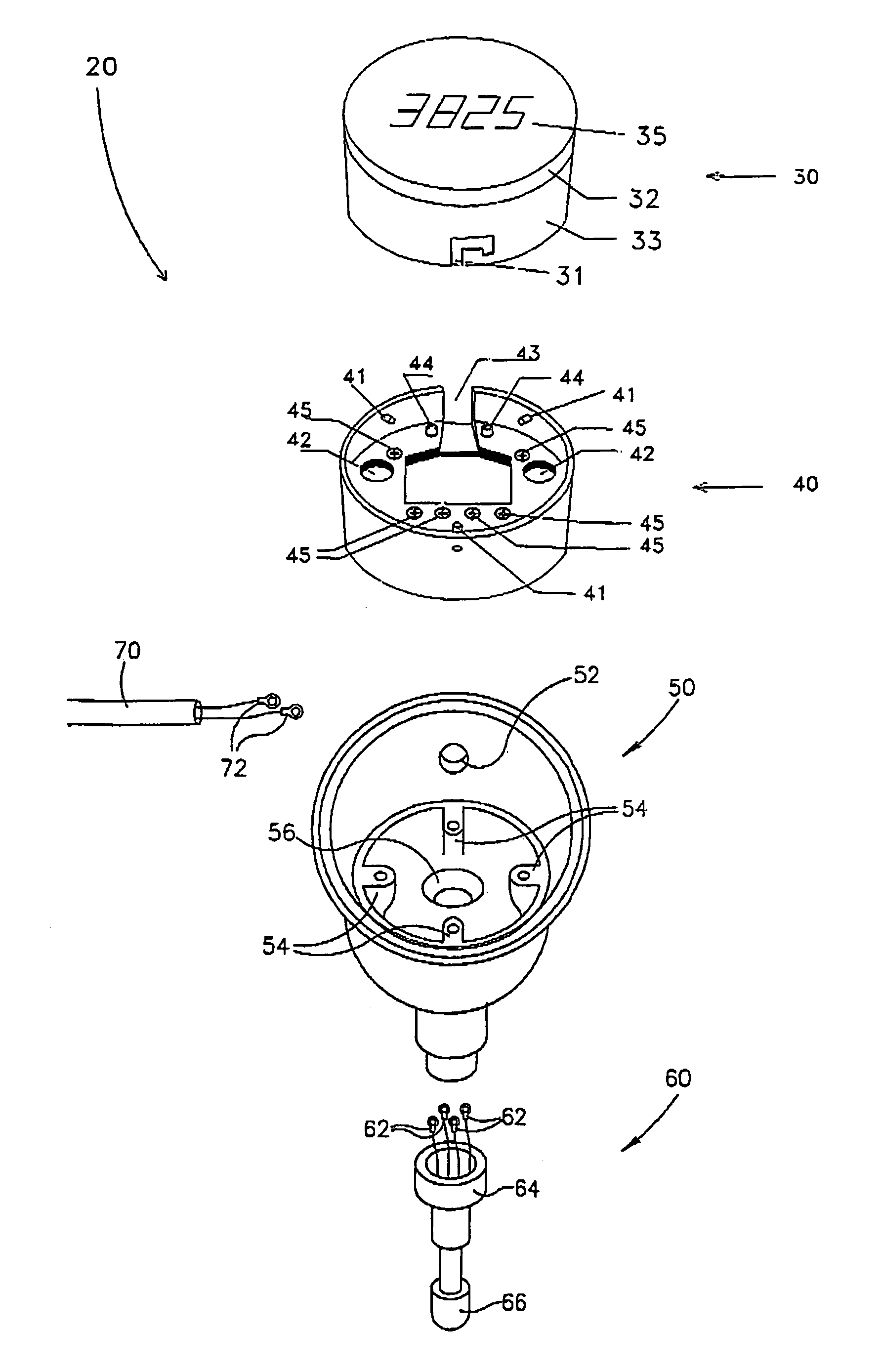
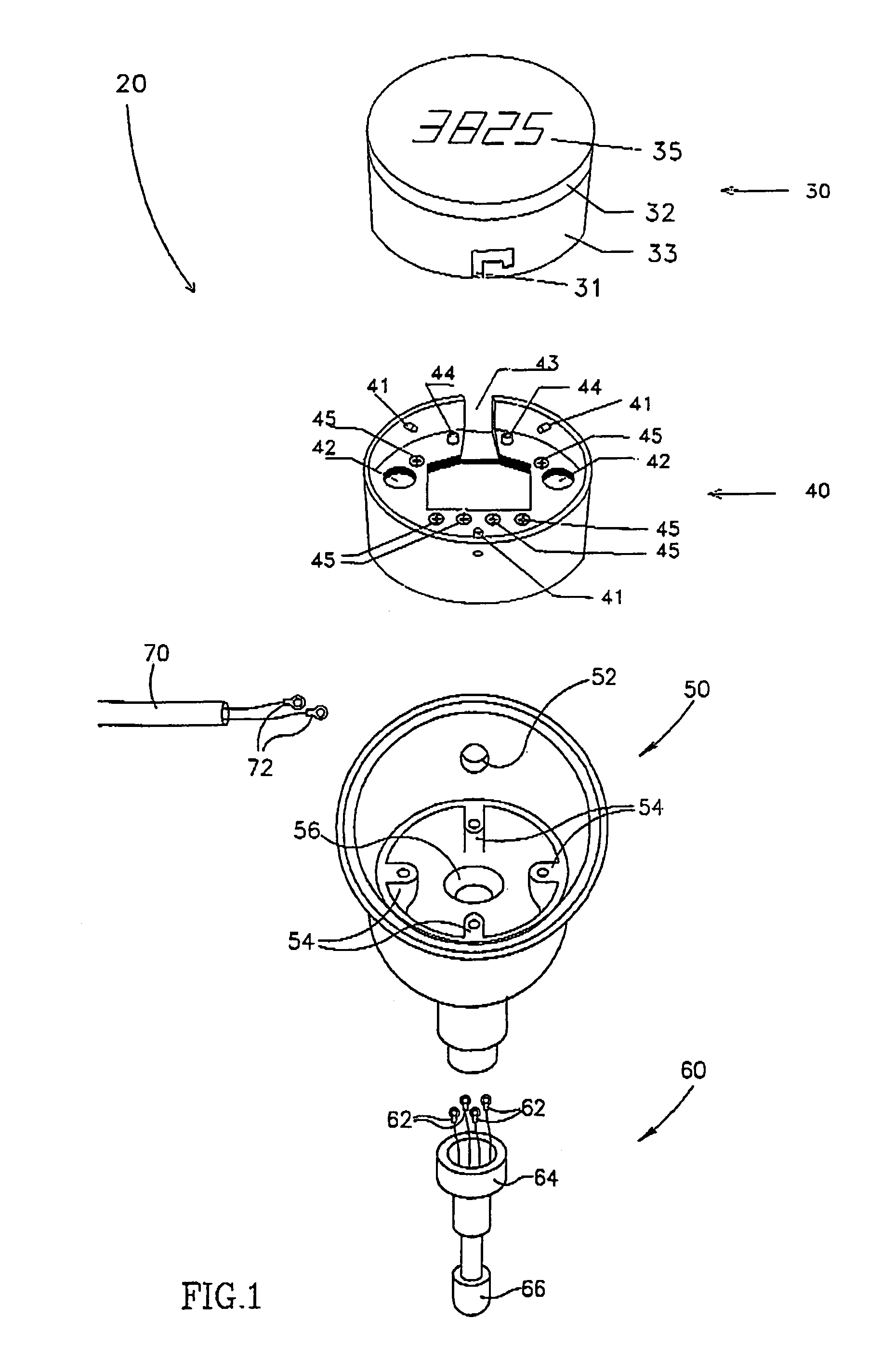
[0032]FIG. 1 is a schematic illustration of an exploded view of an industrial sensing probe 20 in accordance with an exemplary embodiment of the invention. Sensing probe 20 is optionally of a standard size as is known in the art and for which industrial machines that need to be monitored are designed.

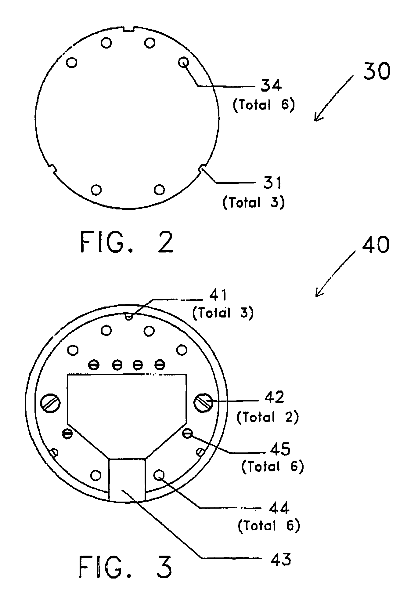
[0033]Probe 20 comprises a connection head 50, a sensor 60, an external wire link 70, all of which are optionally standard components. In addition, probe 20 includes a conversion circuitry component 30 and a matching base socket 40, which, in accordance with an exemplary embodiment of the invention, are different from the single element standard conversion circuitry known in the art.

[0034]In an exemplary embodiment of the invention, connection head 50 comprises an opening 56 adapted to receive sensor 60, an opening 52 adapted to receive an external wire link 70 and a plurality of fixation points, for example, threaded holes 54, for attaching base socket 40. Optionally, threaded holes 54...


PUM


Abstract

A typical probe comprises a sensor, and a connection head that includes a conversion circuit for driving the sensor. The probe communicates with a controller via a two wire DC 4-20 mA link. The conversion circuit is also known as a two-wire transmitter. The conversion circuit and the sensor are connected to each other (and to the external link) via screw terminals usually located at the circuit top face. The invention provides a conversion circuit and a matching base forming plug and socket type connections. On the converter circuit, the connections are moved from the top of the circuit, to the bottom of the circuit, thus clearing space for an integral display. The sensor and the link wires are attached to the base socket. The conversion circuit fits into the socket in only a single orientation, thus ensuring correct coupling of the wires to the circuit elements.

Description

CROSS-REFERENCE TO RELATED APPLICATIONS[0001]The present application is a continuation-in-part application of and claims priority under 35 U.S.C. § 120 from International Application No. PCT / IL02 / 00746, which has an international filing date of Sep. 9, 2002 and is hereby incorporated by reference. International Application No. PCT / IL02 / 00746 claims Paris Convention priority from Israel Patent Application No. 145391, which was filed on Sep. 11, 2001.FIELD OF THE INVENTION[0002]The present invention relates to industrial sensing probes.BACKGROUND OF THE INVENTION[0003]Many types of industrial processes are monitored using industrial sensing probes. Such probes are available in standard sizes. A typical probe comprises a sealed connection head that includes an opening for the extension of a probe sensor into the machine and a connection head internal volume in which a conversion circuit for driving the sensor is encased and protected from the environment. The probe can communicate with...

Claims


Application Information

Patent Timeline
IPC IPC(8): G01R15/00G01K7/00G01L7/00G01R1/04G01D11/24G01K1/02
CPCG01K1/024G01D11/24
Inventor ZACAY, ELY
Owner ZACAY ELY
Why Eureka
Try Eureka