Adsorption process for continuous purification of high value gas feeds
a technology of adsorption process and gas feed, which is applied in the direction of chemistry apparatus and processes, separation processes, dispersed particle separation, etc., can solve the problems of not being able to recognize the possibility of rotary contactors being used in high pressure systems to purify gas streams to high purity levels, and still a significant cost involved in providing this regeneration stream
- Summary
- Abstract
- Description
- Claims
- Application Information
AI Technical Summary
Benefits of technology
Problems solved by technology
Method used
Image
Examples
example 1
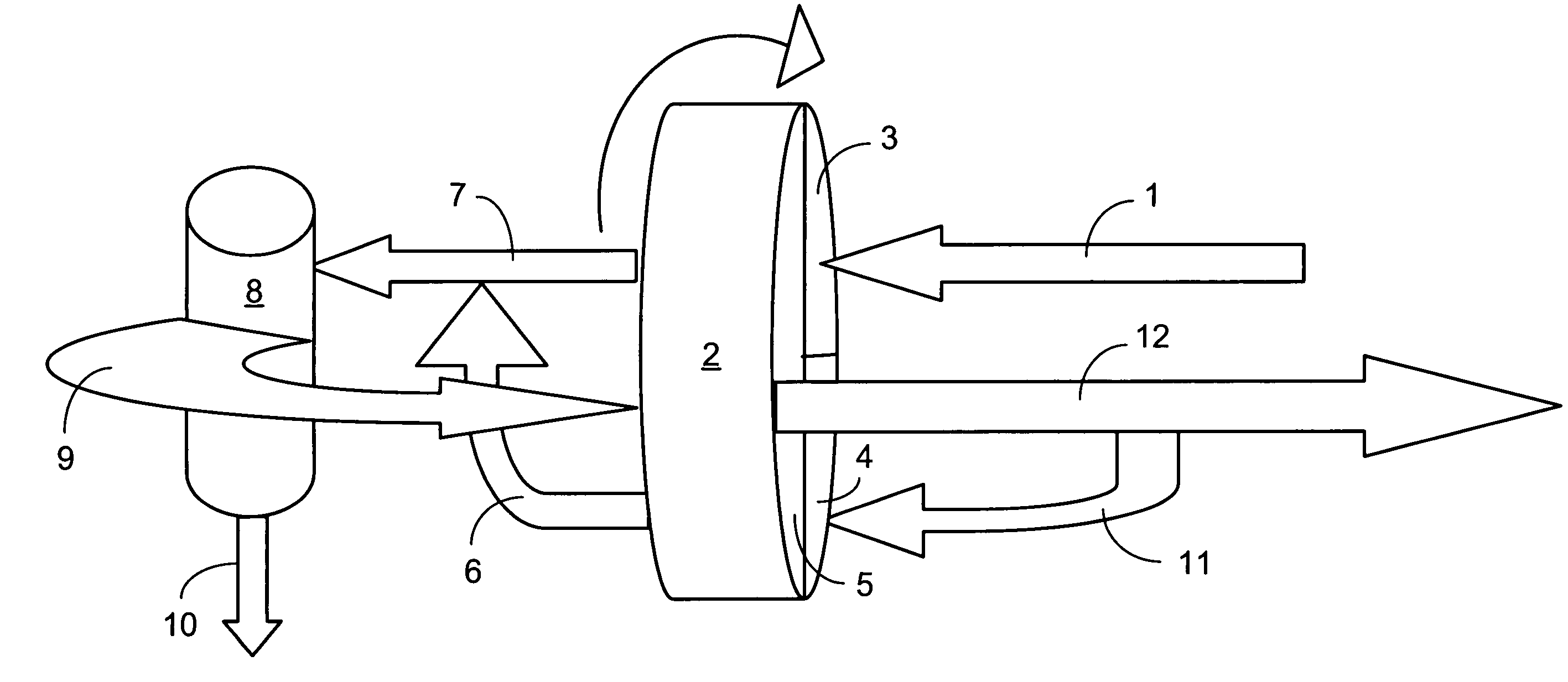
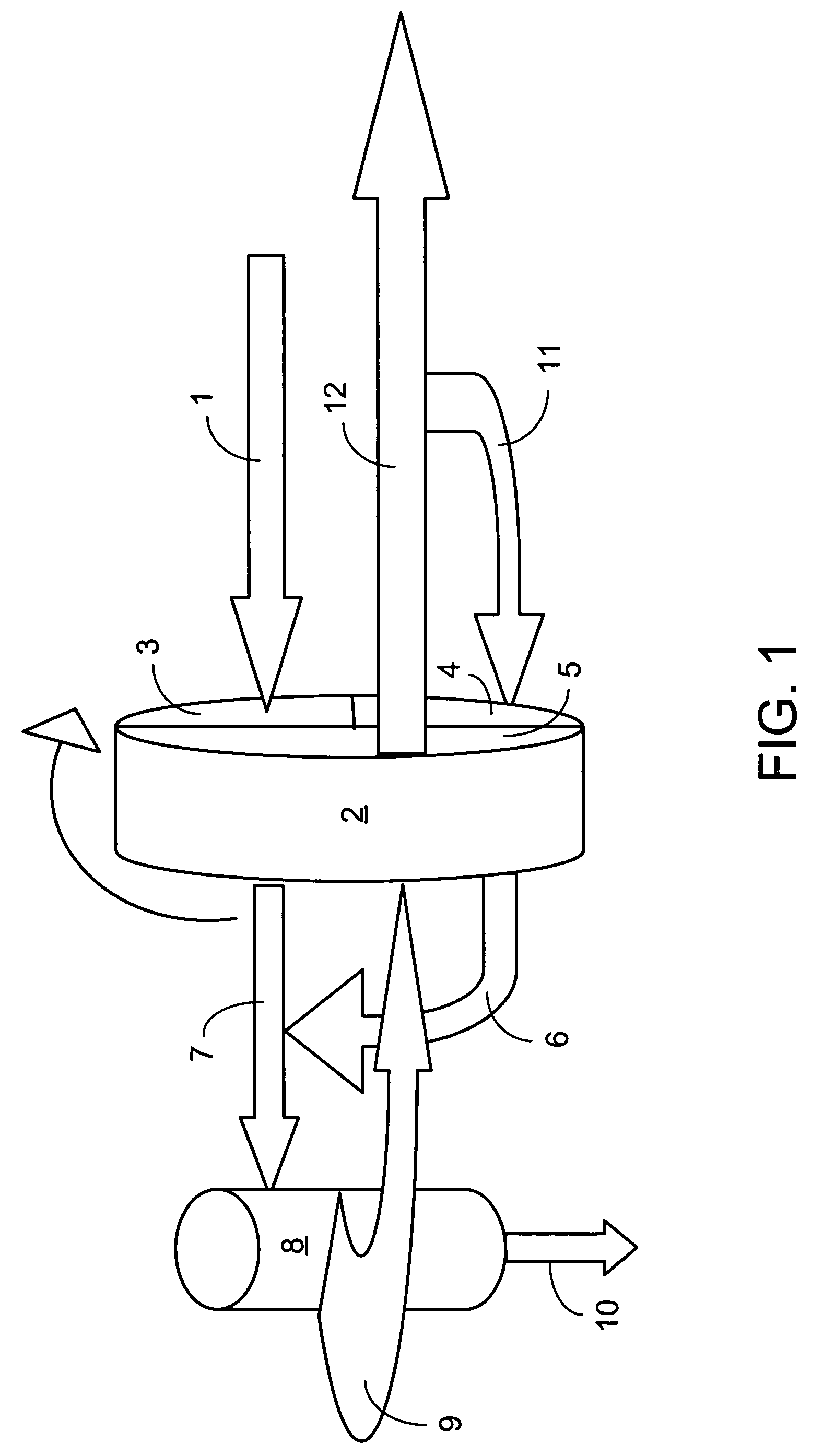
[0051]A wheel having an outer diameter of 103.6 cm (3.4 feet), a hub diameter of 11.43 cm (4.5 inches), and a face area of 0.8332 m2 (8.969 ft2) was used. The adsorbent wheel had an active media volume of 0.4166 m3 (14.713 ft3), a wheel void fraction of 0.73, a rotation rate of 10 revolutions per hour with 360 seconds per cycle, a zeolite fraction of 0.7, a wheel void fraction of 0.73, a paper density of 0.83 grams per cubic centimeter and a media mass of 93.3 kg (205.7 pounds) of paper. The following process conditions were used. The level of water in the feed was reduced from 7270 ppm to 27 ppm (v / v). The adsorption pressure was 7.80 ATM (abs).
[0052]
TABLE 1RegenerationProcess VariablesAdsorption PhasePhaseCooling PhaseGas Velocity110.1 cm / sec184.4 cm / sec68.0 cm / secGas Inlet Temp.34.4° C.180.0° C.34.4° C.Feed Mole7270 ppm(v / v)16875 ppm(v / v)27.2 ppm(v / v)Fraction waterFeed Mole0.007270.0168750.0000272Fractionmole / molemole / molemole / moleAdsorption Step180 seconds158.4 seconds21.6 secon...
example 2
[0054]In this example, a comparison is made between the standard adsorbent beds used to remove impurities from natural gas with the use of an adsorbent wheel in accordance with the present invention. It can be seen that the present invention affords a significant reduction in the quantity of adsorbent required; both due to the continuous operation of an adsorbent wheel and the feasibility of operating with a single adsorbent wheel as compared to the multiple adsorbent beds needed in the present state of the art systems. In a typical three-bed system, over 72,000 kg (150,000 pounds) of adsorbent are required for the three beds, while in an adsorbent wheel system to process the same flow of natural gas, only about 1500 kg (3400 pounds) of adsorbent are needed.
Design Basis: H2O from NG / 3-Bed Design—Comparative Example
[0055]
FeedRegenCoolingFlow Rate / bed (lb mole / hr):2189633023302Pressure (psia)101610161016Temperature (° F.)104550104Step Time (hours)122.51.5Composition (Mol-%):H2O0.10540...
example 3
[0057]In this example, a two-stage high pressure wheel system with no loss of air is shown. All impurities (water) are removed by condensation.
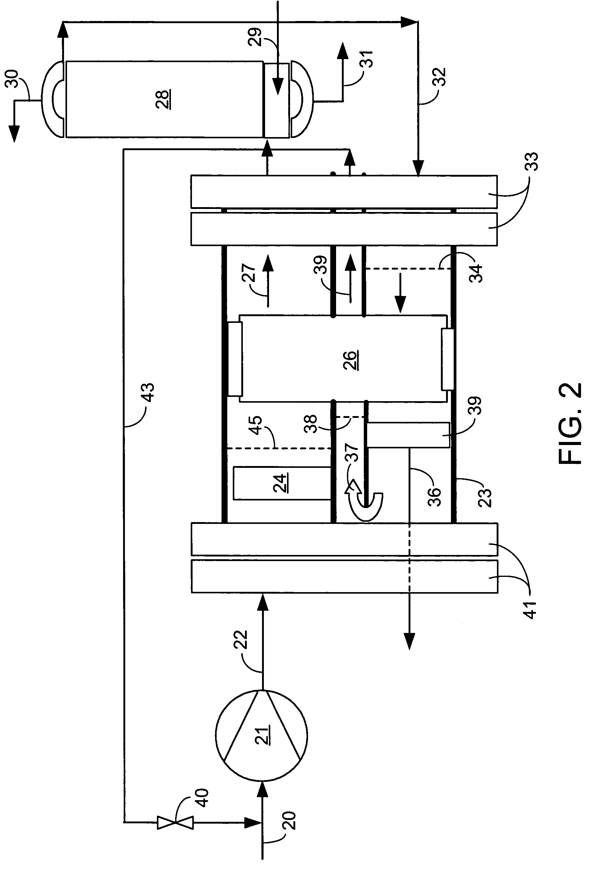
[0058]A dryer for gas that is at moderate to high pressure (ca. 7.8 Atmosphere absolute) consists of a pair of adsorbent wheels. Hot compressed gas exits the final stage of the compressor at a temperature of 150° C. The water content is 23,000 ppm(v) (parts water per million parts of wet air by volume) before entering the two-stage high pressure wheel system. The flow rate of wet air is 3.162 m3 / second (6700 SCFM) [Standard Cubic Feet per Minute where standard conditions are taken as 101.4 kPa (14.7 psia) and 21° C. (70° F.)].
[0059]The hot compressed gas regenerates the 1st wheel. This hot wet air is directed through the regeneration portion of the first of two wheels. In passing through the regeneration sector of the first wheel, the wet air picks up still more water. The exit condition of this air is about 29,000 ppm(v) water. This air will...
PUM
| Property | Measurement | Unit |
|---|---|---|
| temperature | aaaaa | aaaaa |
| diameter | aaaaa | aaaaa |
| length | aaaaa | aaaaa |
Abstract
Description
Claims
Application Information
 - R&D
- Intellectual Property
- Life Sciences
- Materials
- Tech Scout
- Unparalleled Data Quality
- Higher Quality Content
- 60% Fewer Hallucinations
Browse by: Latest US Patents, China's latest patents, Technical Efficacy Thesaurus, Application Domain, Technology Topic, Popular Technical Reports.
© 2025 PatSnap. All rights reserved.Legal|Privacy policy|Modern Slavery Act Transparency Statement|Sitemap|About US| Contact US: help@patsnap.com


