Water jet cutter

a water jet cutter and cutting board technology, applied in the field of water jet cutters, can solve the problems of wear and tear of the surfaces that are impacted, particularly costly with regard to cleaning the cutting table and discharging, and achieve the effect of convenient realization

Inactive Publication Date: 2007-01-23
VOITH PATENT GMBH
View PDF14 Cites 10 Cited by
  • Summary
  • Abstract
  • Description
  • Claims
  • Application Information

AI Technical Summary

Benefits of technology

[0008]The present invention provides a water jet cutter located approximately above a pulper, for the purpose of capturing the trim strip that is separated from the fiber web. In this position in the paper machine, the cutter does not require any discharge and / or vacuum systems. The expensive cutting table may therefore be reduced to a support plate. The support plate is of extremely simple construction and during cutting assures sufficient support of the fiber web in the cutting area. The support plate is equipped with a cutout for the water jet, so that it can pass through unimpeded.
[0009]After the cutting point the separated trim falls off the support plate. After the support plate the flow of the separated trim can be influenced by a guide device, preferably in the form of a guide plate and / or a guide component of the guide plate and / or a compressed air nozzle and / or a water jet nozzle. In order to prevent damage to the fiber web and to counteract contaminant accumulation, the support plate can provide a sliding surface that is as flat as possible and that progresses approximately parallel to the fiber web.
[0010]To achieve perfect cutting quality and a stable cutting process the fiber web can run at a distance along the support plate, at least when uncompromised by the water jet. Because of the flat and preferably smooth sliding surface, sliding of the fiber web during cutting does not present any negative effects. It has been shown to be advantageous if the distance between the fiber web and the sliding surface of the support plate, particularly when uncompromised, is in the range of 0 to 2 mm, preferably between 0 and 0.5 mm.
[0011]The waste and pieces of the fiber web are collected in the pulper and the fiber stock preparation in order to be reutilized. Since the guide device supports the transportation of the separated trim into the pulper, expensive suction devices for guiding the separated trim can be avoided.
[0013]The installation location is particularly easily realized based on the pulper location at the end of a dryer group, preferably after the last dryer cylinder of the dryer group, which is the reason why the water jet cutter preferably is installed there. After leading off of the dryer fabric of the dryer group, the water jet cutter can be located advantageously between one, specifically the last dryer cylinder in the dryer group and a subsequent guide roller.

Problems solved by technology

During operation contamination of the support surfaces, caused by the fibers or the additives in the fiber web occurs.
In addition, the high pressure of the water jet over a period of time leads to wear and tear of the surfaces that are impacted by the water jet.
This is particularly costly with regard to keeping the cutting table clean and with regard to discharging the strip.

Method used


Image

  • Water jet cutter
  • Water jet cutter

Examples


Embodiment Construction

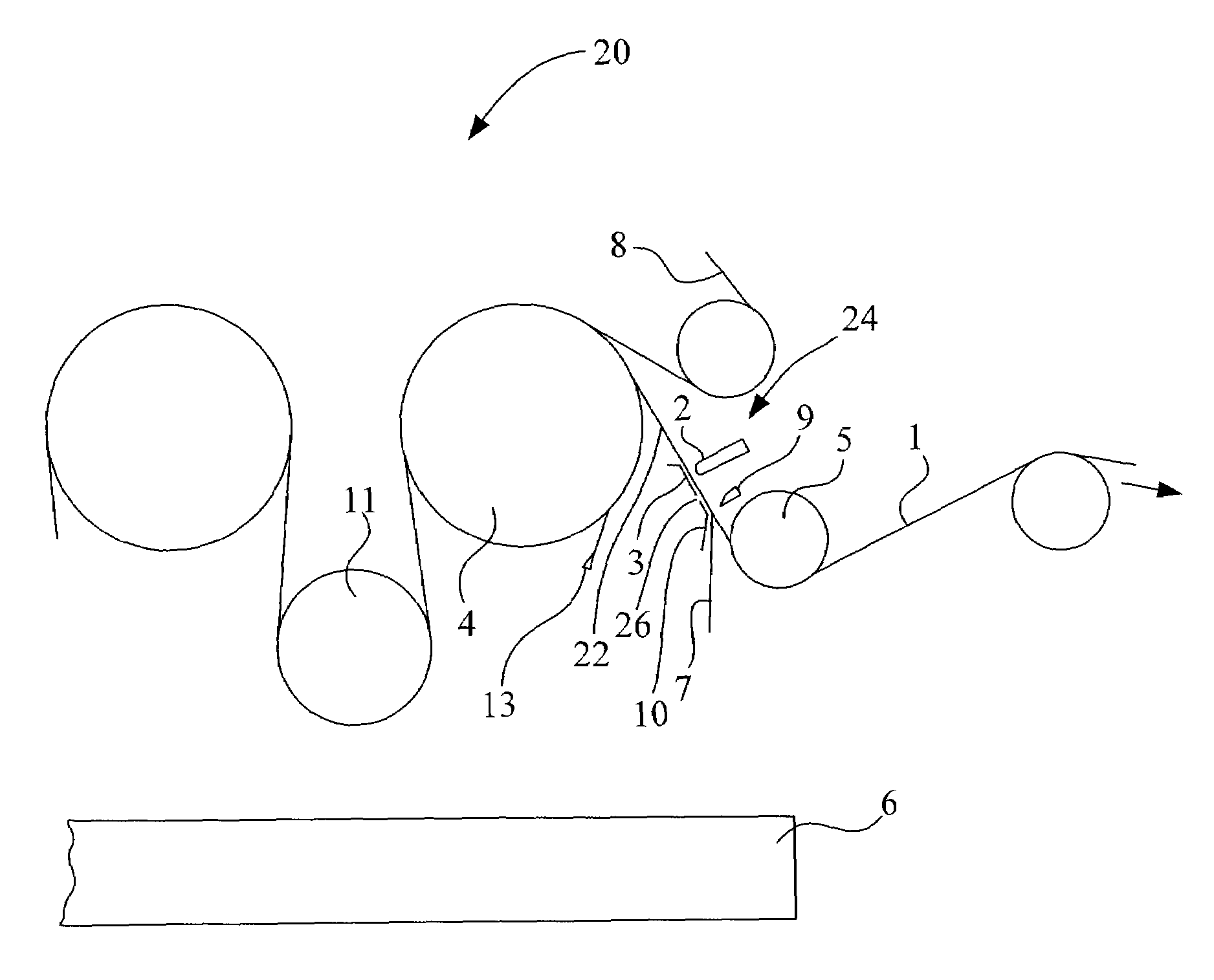
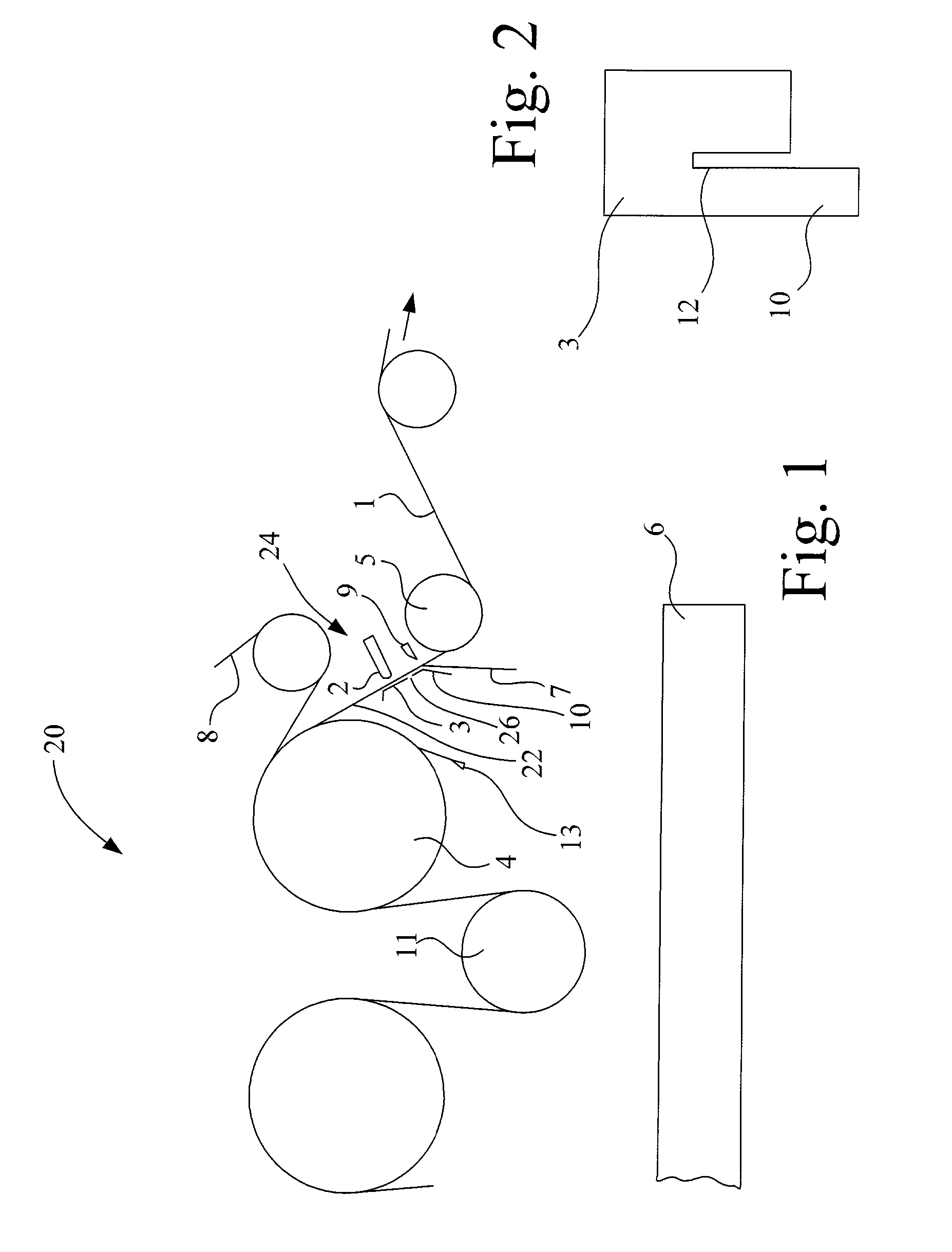
[0018]Referring now to the drawings, and more particularly to FIG. 1, there is shown a dryer section or group 20 of a paper machine wherein fiber web 1 runs usually alternates over heated dryer cylinders 4 and suction equipped guide rollers 11 for the purpose of being dried. Fiber web 1 is carried by at least one dryer fabric 8 of the respective dryer group, whereby fiber web 1 comes into contact with dryer cylinders 4.

[0019]During drying the moisture content of fiber web 1 decreases and the consistency increases. In order to produce clean edges on fiber web 1, the water jet cutter is utilized. Because of the increased consistency of fiber web 1 this can occur in the unsupported section 22 of fiber web 1.

[0020]This is relatively easy at the end of one dryer group, and specifically as shown in FIG. 1, at the end of the last dryer group. After leading off the corresponding dryer fabric 8, fiber web 1 travels into the area of water jet cutter 24. This is located between dryer cylinder ...


PUM

PropertyMeasurementUnit
distanceaaaaaaaaaa
distanceaaaaaaaaaa
distanceaaaaaaaaaa

Abstract

A water jet cutter for separation of a trim strip from a moving paper, cardboard, tissue or other type of fiber web, in a machine for the production and / or conversion of the fiber web, including at least one nozzle whose water jet is directed onto the fiber web. An advantage of the present invention is to simplify the construction of the device while maintaining at least equal operational reliability, and to enable installation above a pulper in order to eliminate the necessity for removal and extraction systems.

Description

[0001]This application claims foreign priority of application 10217723.6 filed in Germany on 20 Apr. 2002.BACKGROUND OF THE INVENTION[0002]1. Field of the Invention[0003]The present invention relates to a water jet cutter for separation of a trim strip from a moving paper, cardboard, tissue or other type of fiber web, in a machine for the production and / or conversion of the fiber web, including at least one nozzle whose water jet is directed onto the fiber web.[0004]2. Description of the Related Art[0005]Because of the high pressure of the water jet and the assurance of a clean cut while avoiding tears or web breaks, the fiber web is supported on the opposite side when cutting by way of a water jet. This support is generally provided by a cutting table. During operation contamination of the support surfaces, caused by the fibers or the additives in the fiber web occurs. In addition, the high pressure of the water jet over a period of time leads to wear and tear of the surfaces that ...

Claims


Application Information

Patent Timeline
Patent Type & Authority Patents(United States)
IPC IPC(8): D21F1/66B26F3/00D21G9/00
CPCD21G9/0063B26F3/004Y10T83/364Y10T83/2066Y10T83/222Y10T83/182Y10T83/0591
Inventor STRAUB, KARLHEINZSOLLINGER, MICHAELPFIFFERLING, RALF
Owner VOITH PATENT GMBH
Why Eureka
Try Eureka