
Far-field RF power extraction circuits and systems

a far-field rf and power extraction technology, applied in the field of power extraction, can solve the problems of reducing reducing the efficiency of the extraction circuit, so as to achieve the effect of optimizing the performance of the extraction circui

Active Publication Date: 2007-01-23
MASSACHUSETTS INST OF TECH
View PDF4 Cites 130 Cited by
  • Summary
  • Abstract
  • Description
  • Claims
  • Application Information

AI Technical Summary

Benefits of technology

[0006]A method and apparatus for performing far-field power extraction are disclosed. The method includes receiving an electromagnetic radiation signal, rectifying the signal to produce a direct current (D.C.) voltage and providing the D.C. voltage to a circuit. A far-field power extraction circuit includes an antenna for receiving an electromagnetic radiation signal, a rectifier for rectifying the electromagnetic radiation signal. The circuit may further include a charge pump for amplifying the rectified voltage, an impedance matching network for coupling the antenna to the rectifier and a feedback tuning circuit for optimizing performance of the extraction circuit.

Problems solved by technology

The operating range of such self-powered devices has been severely limited by the failure of existing power extraction techniques to successfully extract power from radio frequency (RF) signals having relatively low power levels.
Converting RF energy from RF signals at different frequencies is a relatively difficult problem particularly when the RF signals have relatively low power levels.
Fundamentally, this problem arises because frequency conversion is generally a nonlinear operation, but all practical systems are essentially linear for small signals.
In addition, nonlinear devices normally used for rectification have exponential nonlinearities with relatively large “dead zones” near the origin, i.e., nonlinear devices can be non-responsive in response to signals having voltage and current levels which are close to zero.
This limitation precludes the use of exotic devices and structures.

Method used

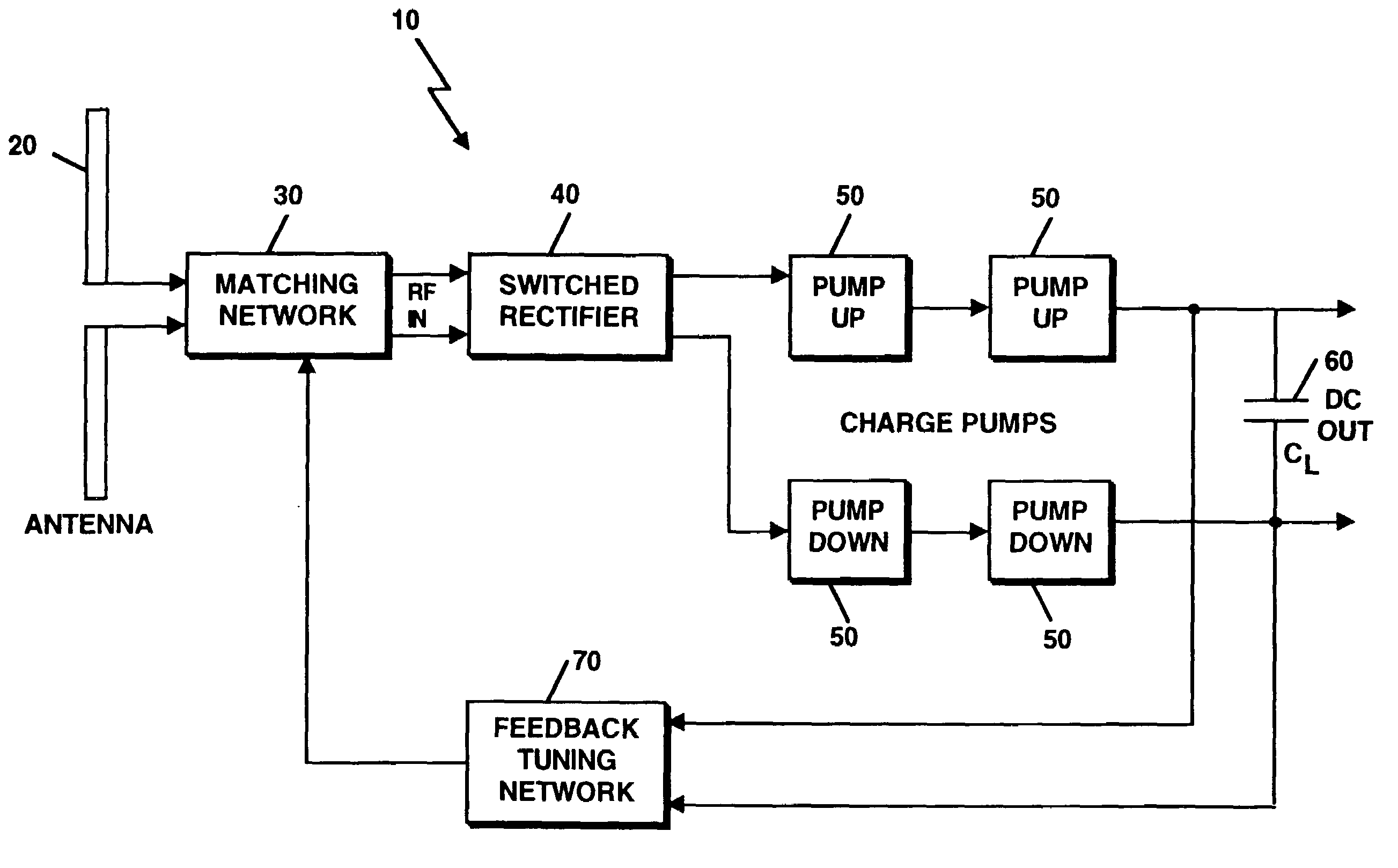

Image

  • Far-field RF power extraction circuits and systems
  • Far-field RF power extraction circuits and systems
  • Far-field RF power extraction circuits and systems

Examples


Embodiment Construction

[0020]The present invention comprises various combinations of different circuits and techniques to efficiently extract power from electromagnetic signals having relatively low electromagnetic field strengths in the far field of the transmitter, thereby substantially reducing the power threshold required for operation of self-powered devices.

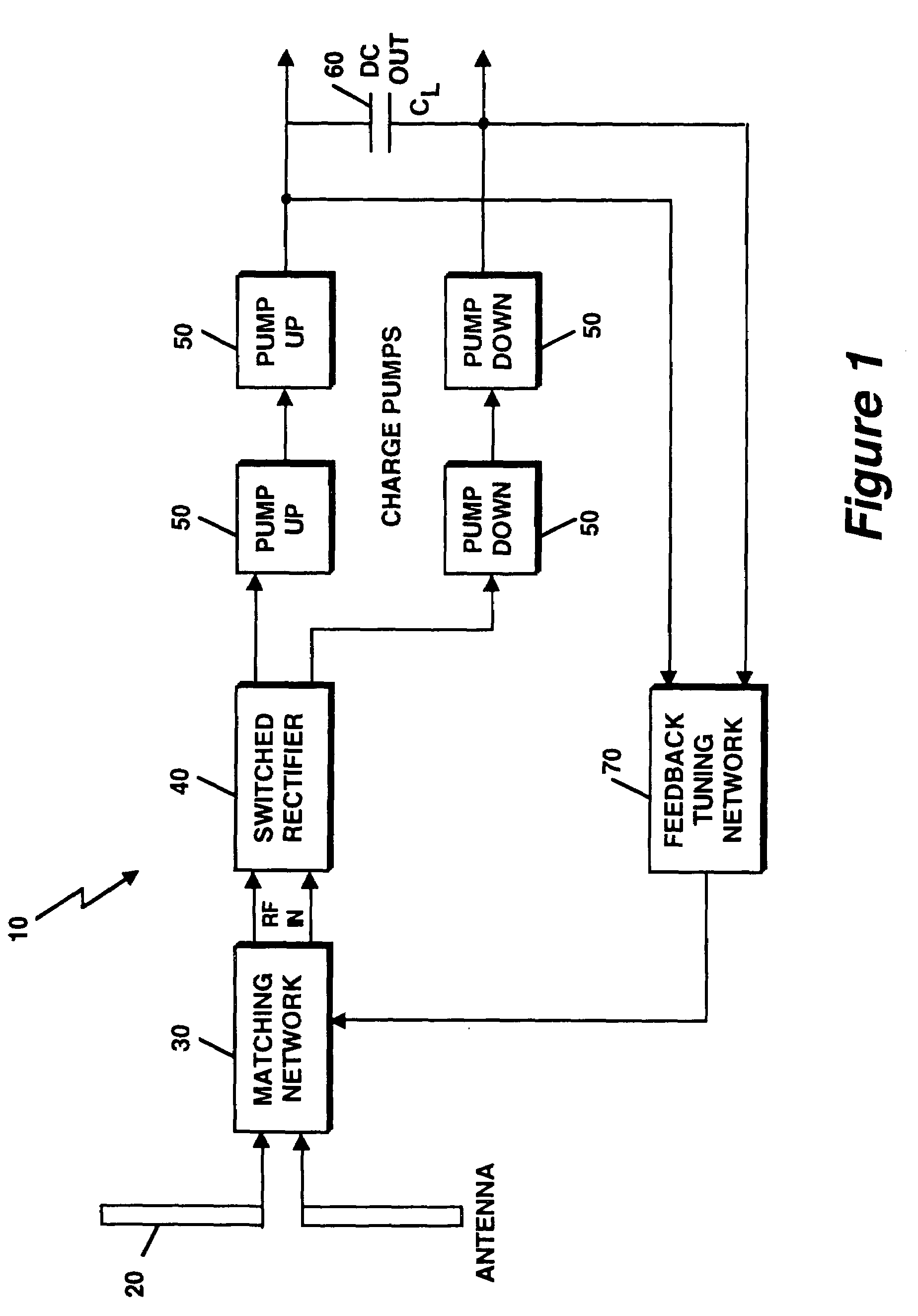
[0021]Referring now to FIG. 1, a block diagram of a system 10 for extracting power from electromagnetic radiation includes an antenna 20 for receiving a radio frequency (RF) signal from which direct current (DC) power will be harvested. A matching network 30 is coupled to the antenna 20 to impedance match the antenna 20 to the remainder of the system, thereby obtaining efficient power transfer. A switched rectifier 40 operates on the impedance matched differential RF signal and converts the signal to one or more DC levels. The output of the switched rectifier 40 is coupled to a group of charge pumps 50, which increase the DC levels of the voltage...


PUM


Abstract

A method and apparatus for performing far-field power extraction are presented. The method includes receiving an electromagnetic radiation signal, rectifying the signal to produce a direct current (D.C.) voltage and providing the D.C. voltage to a circuit. A far-field power extraction circuit includes an antenna for receiving an electromagnetic radiation signal, a rectifier for rectifying the electromagnetic radiation signal. The circuit may further include a charge pump for amplifying the rectified voltage, an impedance matching network for coupling the antenna to the rectifier and a feedback tuning circuit for optimizing performance of the extraction circuit.

Description

CROSS REFERENCE TO RELATED APPLICATIONS[0001]Not Applicable.STATEMENT REGARDING FEDERALLY SPONSORED RESEARCH[0002]Not Applicable.FIELD OF THE INVENTION[0003]The present invention relates generally to power extraction and more particularly to circuits and systems for extracting power from radio frequency (RF) signals.BACKGROUND OF THE INVENTION[0004]Devising efficient methods for extracting DC power from electromagnetic radiation has become an important necessity for a number of applications involving self-powered devices, such as Radio Frequency Identification (RFID) tags and bionic implants. The operating range of such self-powered devices has been severely limited by the failure of existing power extraction techniques to successfully extract power from radio frequency (RF) signals having relatively low power levels. The problem of extracting DC power from electromagnetic radiation has two basic parts: collecting the incident radiated power, and then converting the collected power ...

Claims


Application Information

Patent Timeline
Patent Type & Authority Patents(United States)
IPC IPC(8): G08B1/08
CPCH01Q1/2225H01Q1/248H01Q9/28H02J17/00H02M7/219H01Q23/00Y02B70/1441Y02B70/10H02J50/27H02J50/80
Inventor MANDAL, SOUMYAJITSARPESHKAR, RAHUL
Owner MASSACHUSETTS INST OF TECH
Learn More