Digital actuator control and method

a digital actuator and control method technology, applied in the field of digital electromechanical control, can solve the problems of inability to meet current track pitch requirements, general slowness of stepper motor actuators, and unsuitable approach, and achieve the effects of increasing the degree of flexibility in choosing, increasing the precision and accuracy of actuator movement control functions, and speeding up sample rates

Inactive Publication Date: 2007-01-23
TEXAS INSTR INC
View PDF13 Cites 2 Cited by
  • Summary
  • Abstract
  • Description
  • Claims
  • Application Information

AI Technical Summary

Benefits of technology

[0013]The invention provides technical advantages including but not limited to increased precision and accuracy in actuator movement control functions using digital methods and circuitry. The digital approach of the invention provides a higher degree of flexibility in choosing the exact method of control, e.g. for faster sample rates accommodating higher bandwidth control. These and other features, advantages, and benefits of the present invention will become apparent to one of ordinary skill in the arts upon careful consideration of the detailed description of representative embodiments of the invention in connection with the accompanying drawings and tables.

Problems solved by technology

Stepper motor actuators are generally slow, blind to track position, incapable of meeting current track pitch requirements, prone to misalignment, and are sensitive to variations in temperature.
This approach is not desirable however, because it requires additional current to keep the heads on track over the middle of the disk.
Additional problems arise in the control of the actuators.
Therefore abrupt or imprecise movements of the actuator when parking or unparking can result in damage to the heads, data, or disks.
Problems with imprecisely controlled movements in particular can arise due to the variability in the relative velocity and position of the actuator and platter.
This approach has the disadvantage of causing the actuator motor to continuously accelerate for as long as the actuator motor current remains uninterrupted.
Excessive acceleration of the actuator motor can cause damagingly abrupt actuator movements as in slamming into a fixed “crash stop” at an excessive velocity.
This approach has the disadvantage of being unresponsive to changes in the load on the actuator motor.
Load changes may occur during normal operation for a number of reasons, for example, when the heads are moved up a parking ramp, the load on the motor tends to increase.
The increased load may cause the head to move more slowly, causing an overall loss of speed in the operation of the actuator arm.
The lack of flexibility and area requirements of the analog circuitry hamper the effectiveness of such efforts.

Method used


Image

  • Digital actuator control and method
  • Digital actuator control and method
  • Digital actuator control and method

Examples


Embodiment Construction

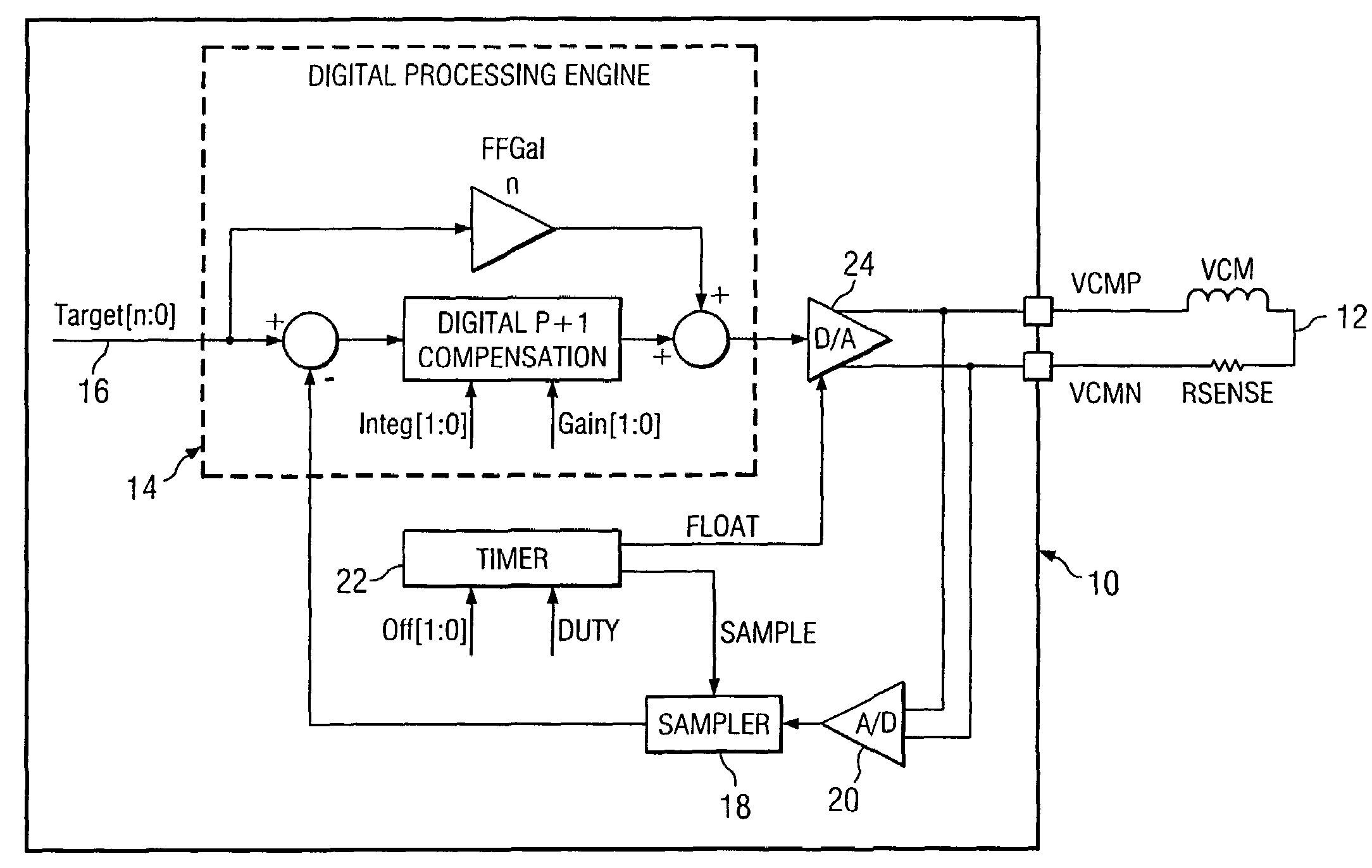
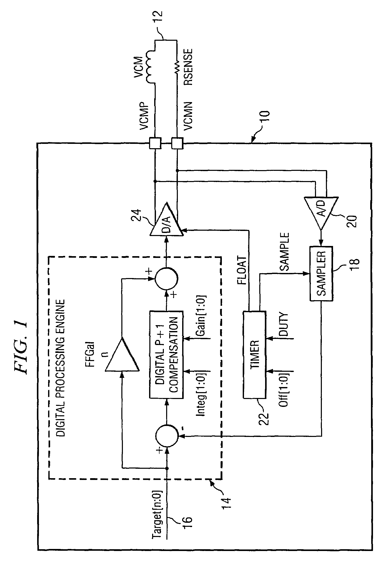
[0020]In general, the invention samples the actuator voltage to dynamically determine the actuator velocity. The compensation needed in order to adjust the voltage across the actuator for improved actuator control is output, and the correct voltage is applied.

[0021]First referring primarily to FIG. 1, a schematic block diagram illustrates an example of a preferred embodiment of apparatus implementing the invention. In the circuit 10 shown, the actuator voltage Vmtr is sensed at the actuator motor 12. A digital processing engine 14 is electrically connected to process the actuator voltage Vmtr and a desired target actuator voltage Vtgt 16 as further described. The sensed actuator voltage Vmtr is typically sampled using a sampler 18, in this case shown connected to an analog-to-digital converter 20. The A / D converter 20 facilitates digital sampling of the analog actuator voltage Vmtr in order to permit the digital processing engine 14 to be used to provide more rapid and accurate proc...


PUM

PropertyMeasurementUnit
actuator voltageaaaaaaaaaa
velocity erroraaaaaaaaaa
voltageaaaaaaaaaa

Abstract

Disclosed are methods and apparatus for digital control of a head-disk assembly actuator with dynamic velocity compensation. In preferred methods of the invention steps are disclosed in which, the actuator voltage in an HDA is sampled and a velocity error is determined. The voltage applied to the actuator is compensated for the velocity error. Disclosed methods of the invention also include steps for measuring the actual voltage at the actuator motor and alternatively, for calculating the actuator motor voltage using digital processing techniques. A digital voltage command is then provided for applying compensated voltage to the actuator motor. Apparatus for implementing the methods of the invention in a hard drive assembly having an actuator motor is also described. The apparatus includes a sampler for sampling an actuator motor voltage, a timer, and a digital processing engine for receiving a target actuator voltage command and the digital actuator motor voltage sample and for outputting a digital voltage command for controlling the actuator motor.

Description

TECHNICAL FIELD[0001]The invention relates to digital electromechanical controls in hard disk assemblies. More particularly, the invention relates to methods and apparatus for implementing control of an actuator with dynamic velocity compensation in disk drive systems.BACKGROUND OF THE INVENTION[0002]The most common form of data storage for computers, hard disk drives in general share a similar basic head-disk assembly (HDA) structure. The actual disks, or platters, are traditionally made of a light alloy, glass or ceramic material coated with a very thin layer of magnetic medium. The magnetic layer has domains of magnetized areas oriented to store information through the use of read and write heads. Multiple platters on a disk drive are separated by disk spacers and are affixed to a rotatable spindle attached to a motor. The spindle is able to rotate all of the platters in unison. The motor is connected to a feedback loop to ensure the correct rotating speed, which may be on the or...

Claims


Application Information

Patent Timeline
Patent Type & Authority Patents(United States)
IPC IPC(8): G11B5/55G11B21/02
CPCG11B5/5526
Inventor ROTE, JOHN KEVINCHEN, LIYONG
Owner TEXAS INSTR INC
Why Eureka
Try Eureka