Video safety detector with projected pattern

a safety detector and video technology, applied in the field of safety/security systems, can solve problems such as pattern distortion, and achieve the effect of avoiding false alarms and superior approaches to security

Inactive Publication Date: 2007-01-23
COGNEX CORP
View PDF43 Cites 66 Cited by
  • Summary
  • Abstract
  • Description
  • Claims
  • Application Information

AI Technical Summary

Benefits of technology

[0024]Intruding objects can be determined according to the invention without using sensors that must be specially designed, placed, or calibrated for each different type of object to be protected. The system does not rely upon any moving mechanical parts subject to the rigors of wear and tear. It is not necessary for the invention to be placed very close to, or in contact with the hazard, as would be necessary for mechanical sensors. Machine vision systems offer a superior approach to security and safety sensors by processing images of a scene to detect and quantify the objects being viewed. Machine vision systems can provide, among other things, an automated capability for performing diverse inspection, location, measurement, alignment and scanning tasks. In addition, the operation is largely immune from problems caused by small contrast differential between the object and the background.
[0025]Another feature of the invention is the ability to discriminate shadows from objects, to avoid false alarms. In addition, the use of a near-IR light source offers the feature of additional illumination without the drawbacks of visible light, such as reflections, or visible texture on the floor or other objects in the target area. Similarly, near-IR is completely invisible and can be operated in what would otherwise appear to humans to be total darkness. Another feature of the invention is the ability to automatically store (and archive) digitized images of the scene in which an infraction of the safety or security rules existed, for later review.

Problems solved by technology

When an object intrudes upon the target area, a part of the pattern will be projected on the object rather than the empty target field, and the pattern thus becomes distorted.

Method used


Image

  • Video safety detector with projected pattern
  • Video safety detector with projected pattern
  • Video safety detector with projected pattern

Examples


Embodiment Construction

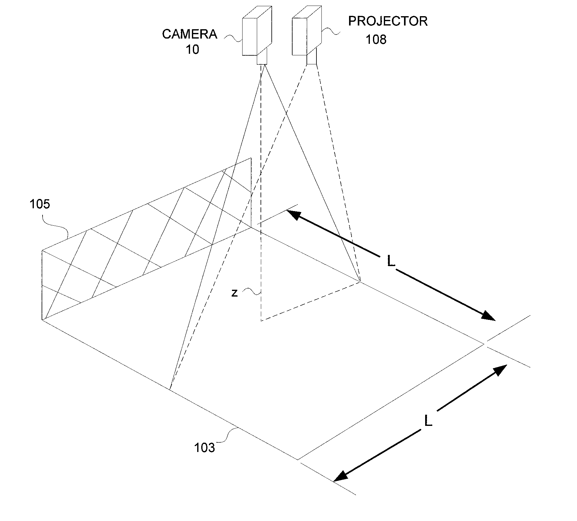
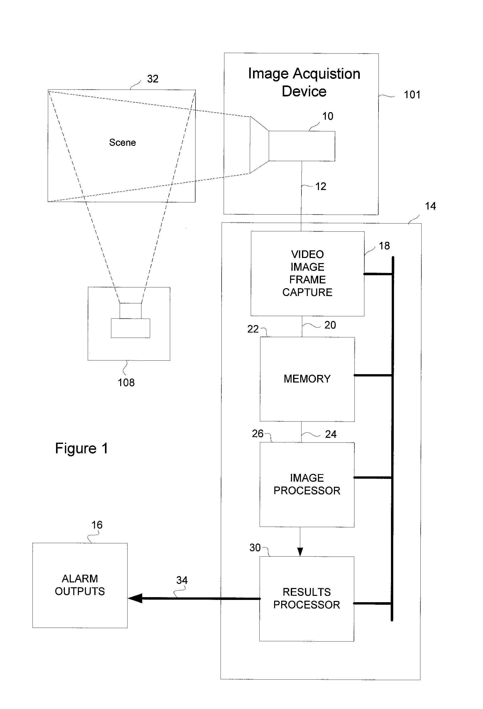
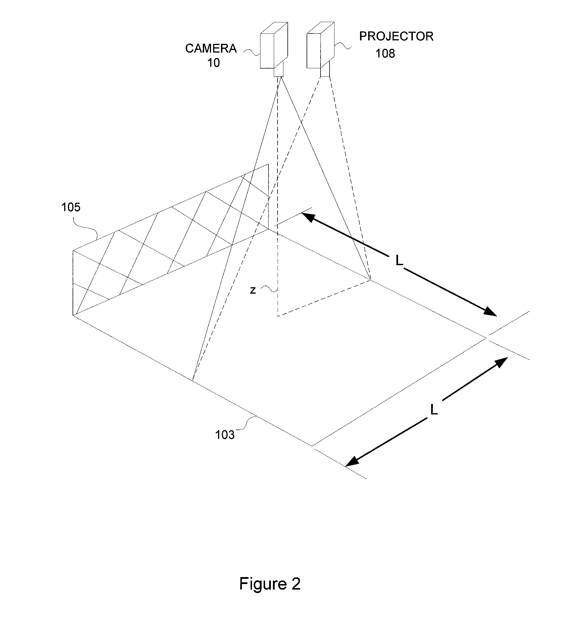
[0031]A vision system implemented in a security and safety embodiment according to the invention is illustrated in FIG. 1. The system incorporates an image acquisition device 101, comprising at least one camera 10, and a projector 108 for illuminating a viewed area with a prescribed pattern. The camera 10 sends a video signal via signal cable 12 to a video safety and security processor 14. The camera 10 is focused on a scene 32 to be monitored. The video safety and security processor 14 includes a video image frame capture device 18, image processor 26, and results processor 30, all of which are connected to a memory device 22.

[0032]Generally, digitized video images 20 from the video image capture device 18, such as a 8100 Multichannel Frame Grabber available from Cognex Corp, Natick, Mass., or other similar device, are stored into the memory device 22. The image processor 26, implemented in this illustrative embodiment on a general-purpose computer processor, receives the stored di...


PUM


Abstract

A two-dimensional (2-D) machine-vision safety-solution involving a method and apparatus for performing high-integrity, high efficiency machine vision. A known structured lighting texture pattern is projected upon a target area. A model image of the pattern on an empty target field is stored during an initial training step. The machine vision safety solution digitally interprets a camera image of the light reflected by the objects in the target area to detect and characterize a pattern in the image. The pattern characterization is then processed to determine if a distortion of the characterization factors is larger than a predetermined threshold, and results in an alarm condition.

Description

FIELD OF THE INVENTION[0001]The present invention relates to safety / security systems, and more particularly to an automated system for observing an area for objects intruding upon a safety / security zone.BACKGROUND OF THE INVENTION[0002]Industrial safety requires protection of operators, maintenance personnel, and bystanders from potential injuries from hazardous machinery or materials. In many cases the hazards can be reduced by automatically sounding an alarm or shutting off a process when dangerous circumstances are sensed, such as by detection of a person or object approaching a dangerous area. Industrial hazards include mechanical (e.g., crush, shear, impalement, entanglement), toxic (chemical, biological, radiation), heat and flame, cold, electrical, optical (laser, welding flash), etc. Varying combinations of hazards encountered in industrial processing can require numerous simultaneous safeguards, increasing capital expenses related to the process, and reducing reliability an...

Claims


Application Information

Patent Timeline
Patent Type & Authority Patents(United States)
IPC IPC(8): G06K9/00
CPCG08B13/1961G08B13/19604
Inventor NICHANI, SANJAYWOLFF, ROBERTSILVER, WILLIAMSCHATZ, DAVID A.
Owner COGNEX CORP
Why Eureka
Try Eureka