Method and apparatus for caged stent delivery

a caged stent and stent technology, applied in the field of caged stent delivery, can solve the problems of inability to tightly crimp the stent, either on the balloon portion of the catheter, or onto its distal end, and no method exists that provides a caged stent delivery system, so as to reduce the exchange time, minimize friction, and restrict the effect of heating

Inactive Publication Date: 2007-01-30
LEVINE MARC ALAN
View PDF15 Cites 184 Cited by
  • Summary
  • Abstract
  • Description
  • Claims
  • Application Information

AI Technical Summary

Benefits of technology

[0012]Similarly, the tubular portion may be adapted to attach to a guidewire alone, which allows access to intraluminal spaces having very small circumferences. This is especially advantageous when trying to deliver stents to intracranial vessels where the catheter is often too large to fit therein. The tubular portion may be connected to the guidewire in any number of ways. For example, the tubular portion may be comprised of a low-temperature heat shrink material to constrict upon heating, thereby tightly attaching itself to the guidewire. Similarly, a locking collet (with or without a set screw), an internal socket (with or without a set screw), or a locking ball may be used. The tubular portion may also be at

Problems solved by technology

Unfortunately, many of the stent delivery methods disclosed still require use of a catheter and a guidewire to deliver the stent to a particular site, even if their exchange is made easier.
One of the problems encountered in using these prior art stents is the inability to tightly crimp the st

Method used


Image

  • Method and apparatus for caged stent delivery
  • Method and apparatus for caged stent delivery
  • Method and apparatus for caged stent delivery

Examples


Embodiment Construction

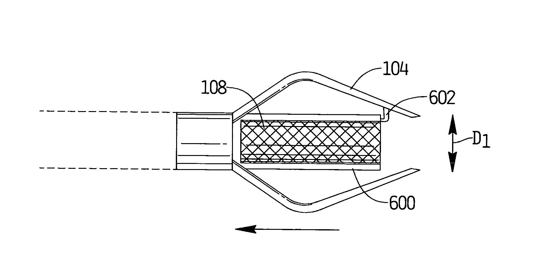
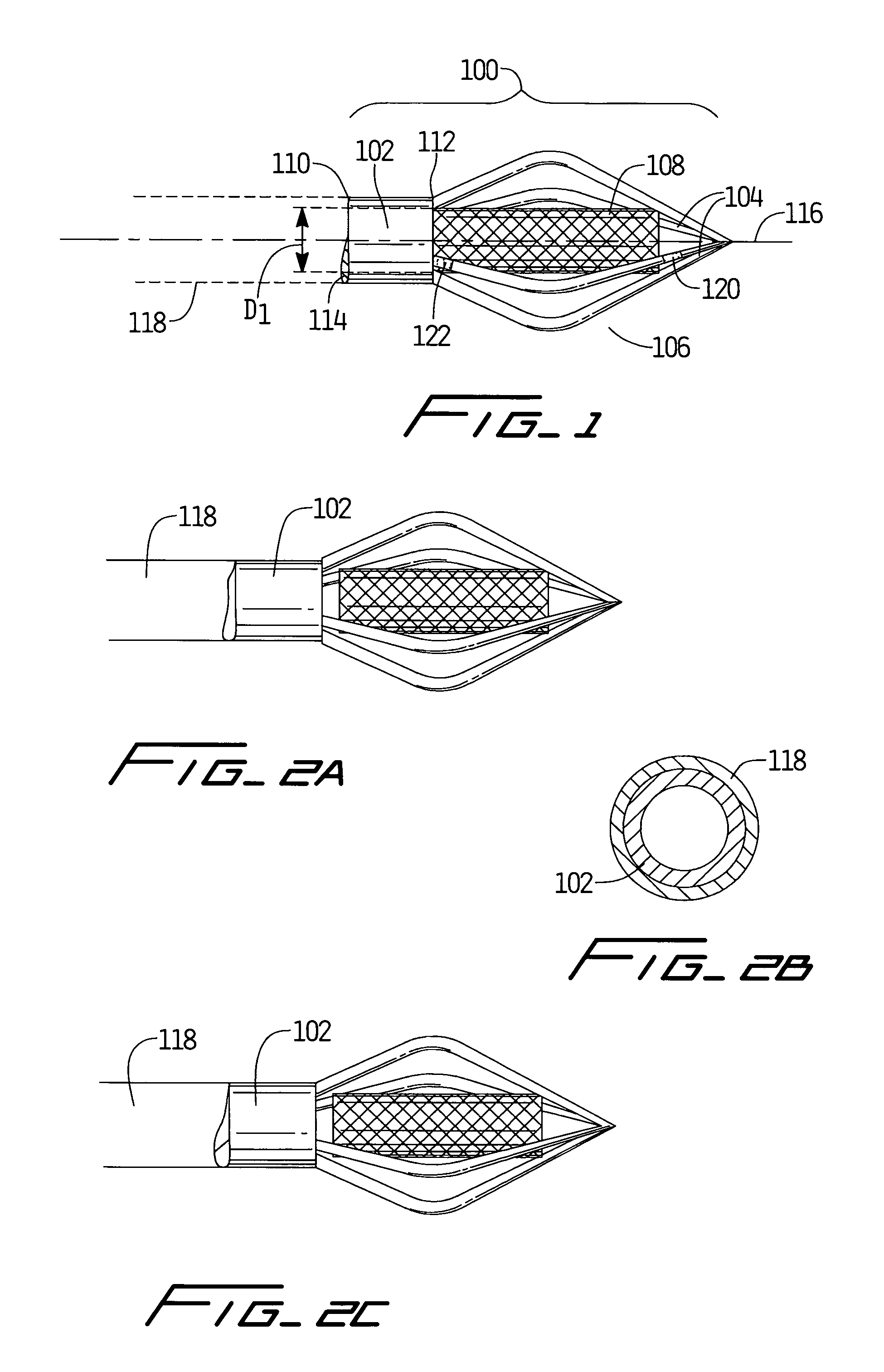
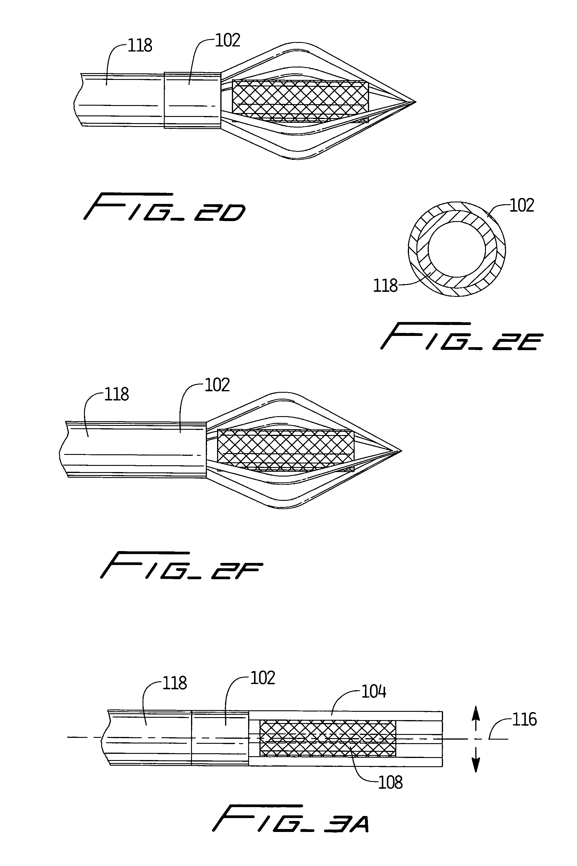
[0033]Turning now to the drawings, wherein like numerals indicate like elements throughout the views, there is shown in FIG. 1 a device 100 for caged delivery of a stent or graft within a body lumen. Device 100 is used to deliver a stent to an intraluminal site and to controllably release it for expansion within a body lumen. The device comprises a tubular portion 102, a plurality of arms 104 attached to the distal end of tubular portion 102, and a mechanism to open the arms. Together, the arms 104 define cage 106 for containing stent 108 in a constricted form, having a smaller diameter, D1, than when deployed within a body cavity lumen, D2.

[0034]In operation, cage 106 carries stent 108, in its smaller diametric form to a preselected treatment site for deployment within a lumen of the body. Arms 104 are then opened, allowing the stent to be released from the cage. As described in greater detail below, the stent may be pushed from the cage to the treatment site, or the stent may simp...


PUM


Abstract

A method and apparatus for caged stent delivery is provided herein. The device can be used to position and deliver any type of stent to a preselected treatment site within an intraluminal cavity. The device comprises a tubular portion, a plurality of arms attached to the distal end of the tubular portion, and a mechanism to open the arms. In operation, the caged device carries a stent in a constricted form to the treatment site for deployment. The arms of the cage are then opened, the stent released and deployed, and the device withdrawn. Several methods are provided to open the arms, including various pullwires, a piston, an electrolytic joint, and an activator. The arms may be constructed of a shape memory alloy and opened when shape memory behavior is effected. The device may be used with conventional catheters or used with a stent-loaded guidewire.

Description

FIELD OF THE INVENTION[0001]The present invention relates to methods for delivering implantable objects within a body cavity. More particularly, the invention relates to an apparatus and method for positioning a stent or graft intraluminally within a target vessel.BACKGROUND OF THE INVENTION[0002]Stents are often employed in a variety of patient treatment and diagnostic procedures. They are usually implanted within blood vessels, biliary ducts and other body lumens to maintain their passageways. For example, a radially self-expanding stent can be deployed in an artery following a percutaneous transluminal coronary angioplasty (PTCA) procedure or a percutaneous transluminal angioplasty (PTA) procedure. The stent resists a tendency in the vessel to close, thus countering acute reclosure and plaque restenosis. A variety of stents, and methods for delivering them, are disclosed in the prior art.[0003]One method frequently described for delivering a stent to a desired intraluminal locati...

Claims


Application Information

Patent Timeline
IPC IPC(8): A61F2/06A61F2/84
CPCA61F2/95A61F2002/9505A61F2/97Y10S623/903
Inventor LEVINE, MARC-ALANHEBERT, STEPHEN
Owner LEVINE MARC ALAN
Why Eureka
Try Eureka