Resistor arrangement, manufacturing method, and measurement circuit

Inactive Publication Date: 2007-01-30
ISABELLENHUTTE HEUSLER
View PDF27 Cites 16 Cited by
  • Summary
  • Abstract
  • Description
  • Claims
  • Application Information

AI Technical Summary

Benefits of technology

[0006]Therefore, the invention is based on the problem of reducing the cost of manufactur

Problems solved by technology

However, a disadvantage in this known resistor arrangement is the fact that to measure several currents, a c

Method used


Image

  • Resistor arrangement, manufacturing method, and measurement circuit
  • Resistor arrangement, manufacturing method, and measurement circuit
  • Resistor arrangement, manufacturing method, and measurement circuit

Examples


Embodiment Construction

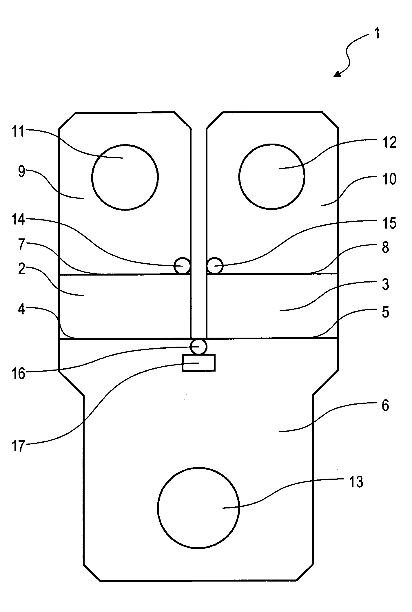
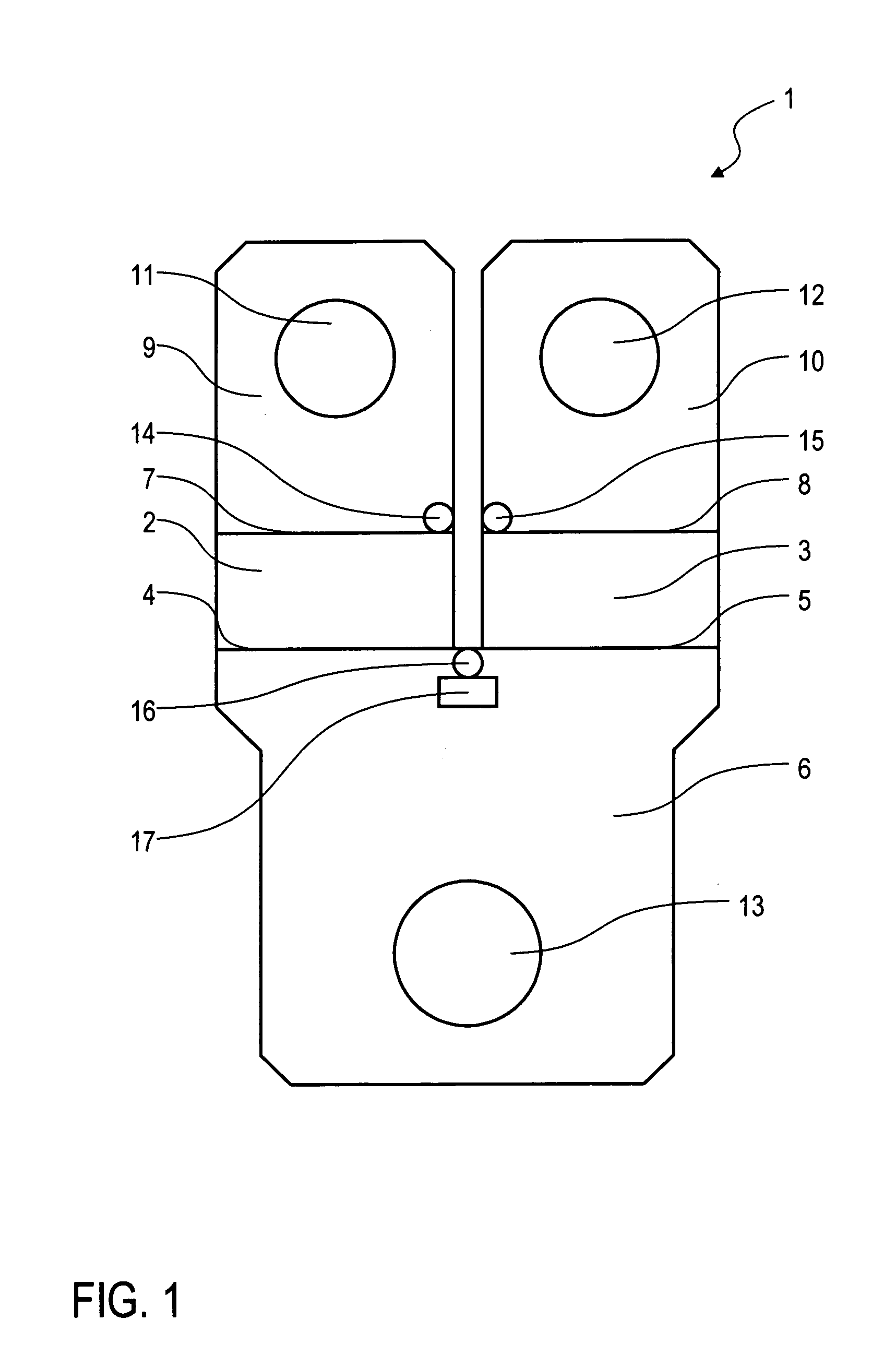
[0050]The diagram in FIG. 1 shows a resistor arrangement 1 according to the present invention, which can be used, e.g., in a vehicle electrical system, for measuring the generator current and the battery current, as will be described in more detail later.

[0051]Here, the resistor arrangement 1 has two resistive elements 2, 3, which are spatially separated from each other and which each consist of a copper alloy (e.g., Manganin®) and exhibit a resistance of, e.g., 100 μΩ.

[0052]The two resistive elements 2, 3 are each connected via a welding seam 4, 5 respectively to a common connection element 6, which consists of copper and is used for current transfer or supply.

[0053]The two resistive elements 2, 3 are further connected via another welding seam 7, 8 each to a separate connection element 9 and 10, respectively, wherein the two connection elements 9, 10 enable separate current supply or current transfer.

[0054]For contacting the connection elements 6, 9, 10, each of these has a current...


PUM

PropertyMeasurementUnit
Electrical conductivityaaaaaaaaaa
Currentaaaaaaaaaa
Electric potential / voltageaaaaaaaaaa

Abstract

The invention relates to a resistor arrangement, especially for current measurement in a vehicle electrical system, with two plate-shaped connection elements separated from each other and a plate-shaped first resistive element, which is arranged between the two connection elements and is electrically and mechanically connected to these elements. According to the invention, at least one of the other plate-shaped resistive elements, which are separated from the first resistive element and which are arranged between one of the two connection elements of the first resistive element and another connection element is connected electrically and mechanically to these connection elements.

Description

BACKGROUND OF THE INVENTION[0001]1. Field of the Invention[0002]The invention pertains generally to a resistor arrangement, and more particularly for current measurement in a vehicle electrical system, and to a method for producing such a resistor arrangement and also to a measurement circuit with such a resistor arrangement.[0003]2. Background Art[0004]Low-impedance resistor arrangements, which can be used for measuring large currents, are known from EP 0 605 800 B1, U.S. Pat. Nos. 6,489,693, and 5,604,477. These known resistor arrangements consist of two connection elements, which are separated from each other and which are at least partially plate shaped, for supplying or transferring current and a plate-shaped resistive element, which is arranged between the two connection elements and which is electrically and mechanically connected to these connection elements, wherein the resistive element is connected to the adjacent connection elements by welding. The known resistor arrange...

Claims


Application Information

Patent Timeline
IPC IPC(8): G01R1/20H01C17/00H01C7/00G01R19/00G01R15/14H01C1/14H01C1/16H01C13/00
CPCG01R1/203H01C1/16H01C1/14Y10T29/49082H01C17/00
Inventor HETZLER, ULLRICH
Owner ISABELLENHUTTE HEUSLER
Why Eureka
Try Eureka