Wavelength routing and switching mechanism for a photonic transport network

a technology of photonic transport network and switching mechanism, which is applied in the field of telecommunication network, can solve the problems of unjustifiable cost and complexity of network, unjustified oeo conversion at the intermediate nodes, and negative impact of point-to-point connectivity on service activation time, so as to achieve cost savings and flexible provisioning

Inactive Publication Date: 2007-01-30
WSOU INVESTMENTS LLC
View PDF1 Cites 46 Cited by
  • Summary
  • Abstract
  • Description
  • Claims
  • Application Information

AI Technical Summary

Benefits of technology

[0017]Advantageously, the wavelength routing and switching mechanism (WRSM) according to the invention offers flexibility of provisioning in that it allows automatic wavelength route selection and path setup across the network infrastructure. The route selection is based on optical constraints, in that it works with real time photonic path and link budgets. WRSM reacts according to these budgets, balancing the network and utilizing regenerative elements where / when necessary.
[0018]A photonic network equipped with the WRSM of the invention allows important cost savings, as a network provider is not required any more to buy extra capacity for future services at the time of network deployment. This is because physical wavelength interfaces are now engineered elements, which do not need to be re-engineered during the provisioning process; the wavelengths can be deployed independent of their provisioning information. The network can be scaled-up only when needed, and the actual provisioning of the wavelength interface can be performed remotely, without human intervention at the physical interface by a simple dial.

Problems solved by technology

However, the current D / WDM networks use point-to-point (pt—pt) connectivity, which means that all channels are OEO (optical-to-electrical-to-optical) converted at each node, which results in very complex and expensive node configurations.
On the other hand, a service needs to be established between two end nodes so that in the majority of cases, OEO conversion at the intermediate nodes adds unjustifiable costs and complexity to the network.
In addition, a point-to-point connectivity impacts negatively on the service activation time, or “time to bandwidth” (TTB).
A pt-pt architecture requires very complex network engineering and planning, resulting in large system turn-up time (in the order of months), involving extensive simulation, engineering and testing.
Adding new services in a pt-pt architecture becomes more complex as the number of channels in the network grows, and therefore costly.
Furthermore, as the network evolves from linear or ring configurations to mesh connectivity, automation of services becomes a difficult task.

Method used


Image

  • Wavelength routing and switching mechanism for a photonic transport network
  • Wavelength routing and switching mechanism for a photonic transport network
  • Wavelength routing and switching mechanism for a photonic transport network

Examples


Embodiment Construction

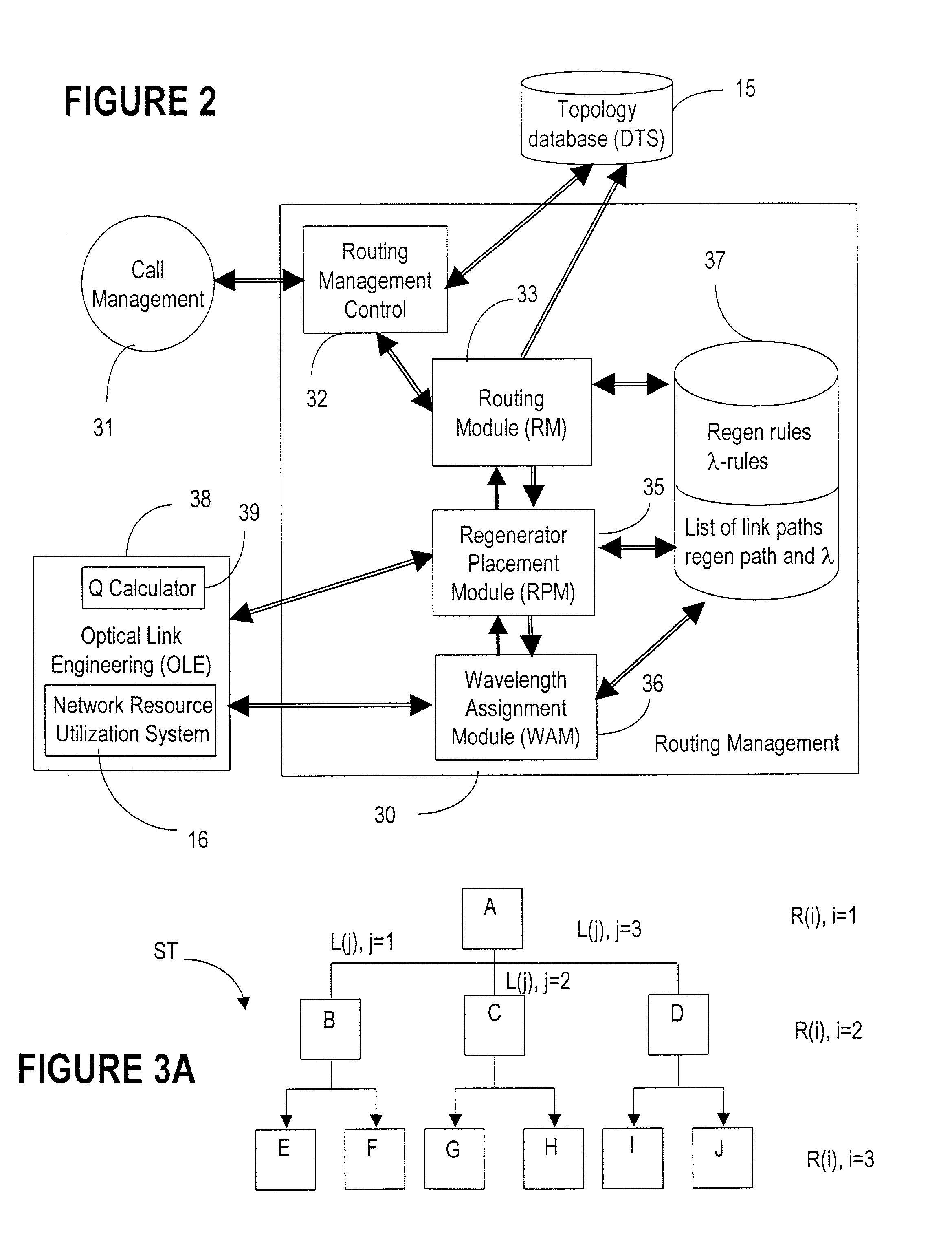
[0032]FIG. 1 shows an example of a photonic network 1, to which the present invention applies. The DWDM layer of network 1 is mesh-connected with flexibility points instead of traditional pt-pt nodes.

[0033]Such a network is illustrated in FIG. 1. The architecture and operation of this network is described in co-pending applications “Architecture for a photonic transport network” (Roorda et al), SN not yet available, docket #1001, filed on . . . , which is incorporated herein by reference.

[0034]To summarize, network 1 comprises bidirectional fiber links 10 connecting a plurality of nodes, which are nodes A, B, C, D, E, F, Z in the example of FIG. 1. The nodes could be switching nodes A, B, E, F, Z, OADM (optical add / drop multiplexing) nodes C, D, and bidirectional optical amplifiers 8 which condition the optical signals. Local traffic 16 originating and terminating on a service platform 7 (e.g. a router, an ATM switch, an EXC, etc.) accesses the network 1 at a switching node or an OA...


PUM


Abstract

A connection between a source node and a destination node is automatically routed and switched in a WDM photonic network, on receipt of a connection request. A switching and routing mechanism selects a plurality of valid link paths using a path tree, where invalid branches are eliminated based on constraints received in the connection request, and on a link and path cost functions. A regenerator placement tree is used for determining a plurality of viable regenerator paths for each valid link path. On the regenerator placement tree, non-viable branches are eliminated based on constraints received with the request and on regenerator availability at the intermediate nodes along the respective path, and on the specification of these available regenerators. Next, the switching and routing mechanism assigns a set of wavelengths to each viable regenerator path, and estimates the performance of the path using a Q estimator. The regenerator paths are ordered according to their performance and the switching and routing mechanism attempts to setup a paths to serve the request, starting with the best path.

Description

FIELD OF THE INVENTION [0001]The invention is directed to a telecommunication network, and in particular to a wavelength routing and switching mechanism for a photonic network.BACKGROUND OF THE INVENTION [0002]The most relevant trends in the optical networking area are the increase in the network capacity and the increase in transmission reach. In response to the exponential growth of Internet use throughout the world, carriers are installing DWDM (dense wavelength division multiplexing) networks, and attempting to scale-up the existing networks by addition of equipment to support new services. It is estimated that expansion of long haul optical communication networks will be in the order of 70–150%, fueled by ever-growing data, and lately video, traffic. Currently, this expansion continues mostly based on improvements to the current transport technologies.[0003]Carriers are also installing ultra-long reach networks, where regeneration of the signal is effected at 3,000 km or more. ...

Claims


Application Information

Patent Timeline
Patent Type & Authority Patents(United States)
IPC IPC(8): H04B10/08H04B17/00H04J14/02
CPCH04J14/0283H04J14/0284H04J14/0241H04J14/0257H04J14/0269H04J14/0246H04J14/0221H04J14/0268
Inventor SMITH, ANTHONY VERNON WALKERTITCHENER, JONATHANGUY, JOHN PETERNADON, ROBERT ALAIN
Owner WSOU INVESTMENTS LLC
Why Eureka
Try Eureka