Storage device

Inactive Publication Date: 2007-01-30
PANASONIC CORP
View PDF12 Cites 1 Cited by
  • Summary
  • Abstract
  • Description
  • Claims
  • Application Information

AI Technical Summary

Benefits of technology

[0010]The present invention was conceived in view of the above problems. An objective of the present invention is to provide a technique for more readily increasing the confidentiality of a storage device, such as an IC card, and more readily reading internal data as necessary.
[0012]With the above structure, memory data stored in a memory is taken in the microcomputer and output to the outside of the storage device, and the microcomputer normally operates, only when a clock signal has a predetermined frequency. Thus, a fraudulent action of analyzing the memory data with a usually-employed low-frequency clock signal is prevented, whereby the confidentiality of data stored in the storage device is improved.
[0017]With the above structures, memory data stored in a memory is readily prevented from being taken in a microcomputer as described above.
[0024]With the above structures, when the detected temperature or the intensity of detected light is not appropriate, memory data is prevented from being taken in a microcomputer. Thus, fraudulent obtainment of information is more readily prevented.
[0027]With the above structures, the timing for inputting memory data into a microcomputer is different in every memory access operation, it is difficult to dismantle and analyze a storage device by touching a transmission path of the memory data with a probe. Thus, the confidentiality of data stored in the storage device is readily improved.

Problems solved by technology

In the case of such a use, the confidentiality of data stored in the storage device is a matter of concern.
Furthermore, there has been a known technique of encrypting data to be stored such that the data cannot be readily decrypted even if it is read out.
However, in the method of collating an inherent number, the IC card is vulnerable to a fraudulent access if the inherent number is revealed.
Moreover, there is a possibility that confidentiality is breached by sequentially inputting a series of numbers.
Further, there is a possibility that the IC card is dismantled and internal data is analyzed by touching a wire with a probe.
In such a case, it is difficult to protect the confidentiality.
In the case where data is encrypted, high confidentiality protection is not necessarily obtained because the level of confidentiality is determined by the encryption strength.

Method used


Image

  • Storage device
  • Storage device
  • Storage device

Examples


embodiment 1

[0042](Embodiment 1)

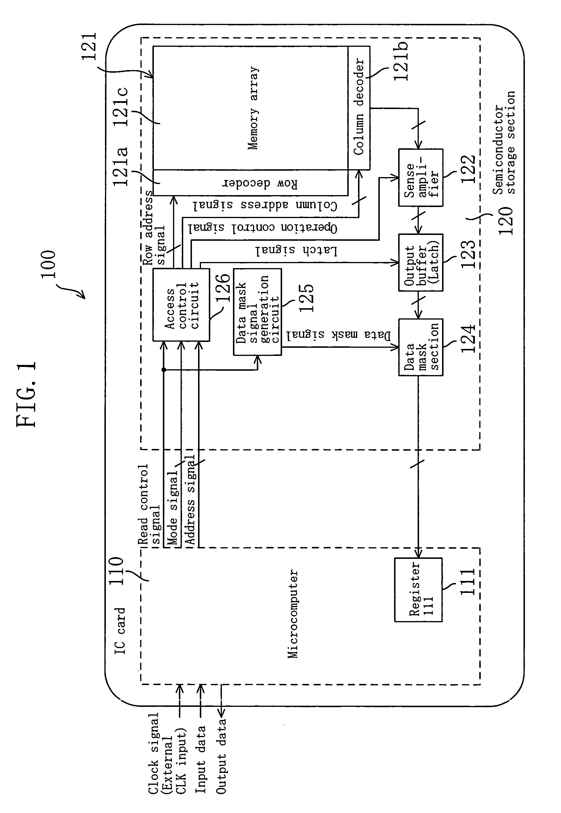
[0043]FIG. 1 is a block diagram showing the entire structure of an IC card 100 according to embodiment 1.

[0044]In the IC card 100 shown in FIG. 1, a microcomputer (processor) 110 includes a register 111 which stores data read from a semiconductor storage section 120 (described later). The microcomputer (processor) 110 performs control of data input / output operations and various data processing in the IC card 100 according to an external clock signal or a clock signal obtained by dividing or multiplying the frequency of the external clock signal. More specifically, the microcomputer 110 writes data supplied from an external device in the semiconductor storage section 120 and outputs data read from the semiconductor storage section 120 or data which has undergone a predetermined process to an external device by executing, for example, a program stored in the semiconductor storage section 120.

[0045]The semiconductor storage section 120 stores programs to be executed...

embodiment 2

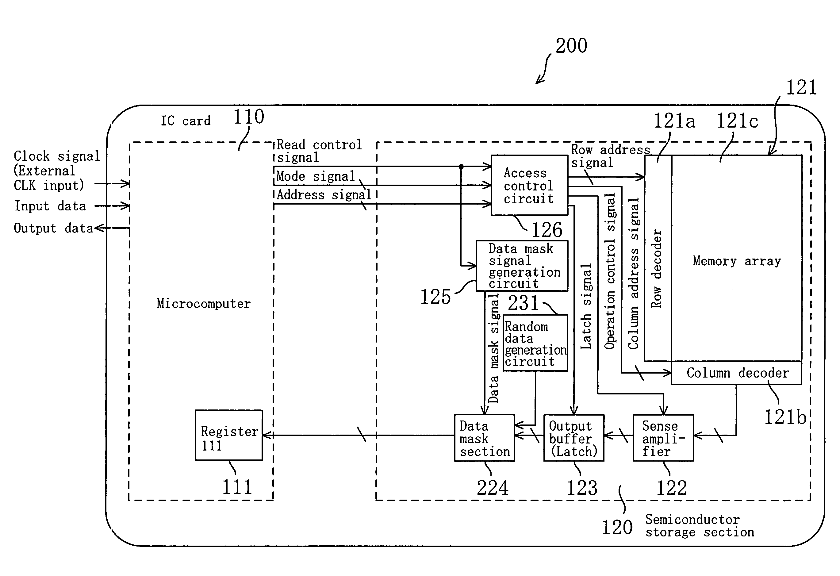
[0067](Embodiment 2)

[0068]Hereinafter, an IC card of embodiment 2 is described. It should be noted that, in the embodiments described below, components having the same functions as those of embodiment 1 are denoted by the same reference numerals, and descriptions thereof are omitted.

[0069]The IC card 200 of embodiment 2 shown in FIG. 5 is different from the IC card 100 of embodiment 1 in that the IC card 200 includes a data mask section 224 in place of the data mask section 124 and further includes a random data generation circuit 231.

[0070]The random data generation circuit 231 outputs a random data signal at a predetermined timing.

[0071]Specifically, referring to FIG. 6, the data mask section 224 includes selectors 224a. The number of selectors 224a corresponds to the number of bits of data.

[0072]With the above structure, as illustrated in FIG. 7, when the data mask signal is at the H level, the data mask section 224 outputs the data signal read from the memory array unit 121 as i...

embodiment 3

[0077](Embodiment 3)

[0078]Referring to FIG. 9, an IC card 300 of embodiment 3 is different from the IC card 200 of embodiment 2 in that the IC card 300 further includes a temperature detecting circuit 331 and includes a data mask signal generation circuit 325 in place of the data mask signal generation circuit 125. The data mask signal generation circuit 325 of embodiment 3 pulls up the data mask signal to the H level at the same timing as that of embodiment 2 only when a temperature detected by the temperature detecting circuit 331 is within a predetermine range.

[0079]With the temperature detecting circuit 331 and the data mask signal generation circuit 325, the microcomputer 110 normally operates only when the detected temperature is in the predetermined range and a clock signal having a predetermined frequency is supplied, but when otherwise, memory data is not read out. Thus, the confidentiality of the memory data is readily more improved.

[0080]Even in the case where a third per...


PUM


Abstract

A data mask section outputs memory data read from a memory array unit for a predetermined time period that is shifted from an edge timing of a clock signal, while a microcomputer takes in the data output from the data mask section at the edge timing of the clock signal. Thus, the microcomputer is capable of appropriately taking in the memory data only when the frequency of the clock signal is within a predetermined range, and accordingly, it is difficult to fraudulently obtain the memory data. Furthermore, the data mask section may output random data, or the like, during a time period other than the predetermined time period. In such a case, it is difficult to analyze the memory data, and the confidentiality of the memory data is improved.

Description

BACKGROUND OF THE INVENTION[0001]The present invention relates to a storage device having a semiconductor memory and a processor, such as an IC card, or the like, and specifically to a technique for improving the confidentiality of data stored in the semiconductor memory.[0002]In recent years, the market of a storage device incorporating a microcomputer and a semiconductor storage, such as an IC card, or the like, has been rapidly increasing, and such a device has been applied to various uses.[0003]Especially, a use of a storage device wherein an IC card, or the like, includes personal data or financial data has been more popular. In the case of such a use, the confidentiality of data stored in the storage device is a matter of concern.[0004]On the other hand, in the course of production of an IC card, or in the case where a defect is found in an IC card already shipped to a market, a company that manufactures IC cards or performs IC card services is frequently required to read data...

Claims


Application Information

Patent Timeline
IPC IPC(8): G06F12/14B42D15/10G06F21/75G06F21/86G06K19/073
CPCG06K19/07363G06K19/073
Inventor MATSUURA, MASANORI
Owner PANASONIC CORP
Why Eureka
Try Eureka