
Electric generation facility and method employing solar technology

a technology of solar energy and electric generation, applied in the field of energy sources, can solve the problems of direct heating, severe drawbacks of chemical plants, and potential ecological impact of altering the natural flow of rivers

Inactive Publication Date: 2007-02-06
POWERSTREAMS
View PDF4 Cites 17 Cited by
  • Summary
  • Abstract
  • Description
  • Claims
  • Application Information

AI Technical Summary

Benefits of technology

"The present invention provides a new and useful electric generation system and method that can produce electricity in an environmentally clean manner. The system includes a solar array, a heat exchanger, a steam engine, and a low temperature turbine generator. The system can also include a thermal storage medium and a water supply reservoir for storing and reusing water. The invention also contemplates a method of producing electricity using a solar array, a heat exchanger, and a steam engine. The technical effects of the invention include improved efficiency, cost savings, and the ability to produce electricity during peak demand."

Problems solved by technology

Solar energy, itself, can cause excited mechanical states resulting in the direct heating due to mechanical vibration, osculation and the like.
Such hydroelectric generation facilities have positive attributes of being a relatively clean source of electricity although they have a disadvantage in the potential ecological impact associated with altering the natural flow of rivers and streams.
However, such chemical plants have severe drawbacks due to the pollutants produced from the burning of large amounts of organic materials.
Again, ecological damage results.
Towards the end of the 20th century however, nuclear power facilities began to fall into disfavor for their potential cataclysmic effects on the environment.
Whereas, if properly controlled and monitored, such facilities could provide relatively clean electricity, human error and the natural deterioration of mechanical systems created the specter of a failure of containment of the thermonuclear process.
The result of loss of containment was understood to have potential catastrophic results on the environment through widespread radiation contamination and the potential medical threat to large populations of humans.
Moreover, such thermonuclear production facilities produced byproducts in the form of spend nuclear materials the storage of which presents significant challenges.
While thermonuclear fusion still appears to be a promising source of energy, science has not yet learned how to harness and control the production of energy from this awesome physical phenomenon.
While there are those who believe that the fusion process will ultimately solve the world's energy needs, that solution remains elusive.
While solar energy presents the opportunity for perhaps the cleanest of all production of electricity, it nonetheless has drawbacks associated with efficiency and weather.
First, the production of electricity, for example, from photoelectric cells, has not yet achieved high efficiency levels although there are increasing improvements into photoelectric that address this efficiency problem.
Even so, such materials currently are relatively expensive so that the production of electricity from solar cells involves a high capital expenditure.
In either of the cases of solar cells or solar collectors, it is better to have unobstructed radiation from the sun so that production of electricity from solar facilities may be seriously impacted by inclimate weather.
Accordingly, solar facilities may only have applicability in environments that enjoy a large number clear days.
In the evening, there is a higher consumption of electricity for use in lighting.
This consumption, however, drops off in the late evening and through the night when people are in bed.
Since many electrical generation facilities produce electricity at a constant level, there are times for any given grid wherein the consumption of electricity may be lower than the ability of the facilities to output power but in many cases the consumption exceeds the capacities of the grid to produce.
Where a power grid purchases electricity from other grids, it is well known that the price per unit can soar to many times the cost of a unit during non-peak demand.

Method used


Image

  • Electric generation facility and method employing solar technology
  • Electric generation facility and method employing solar technology
  • Electric generation facility and method employing solar technology

Examples


Embodiment Construction

[0043]The present invention broadly concerns electric generation systems and stations to produce electricity for supply to a power grid. More particularly, the present invention is directed to a solar powered electric generation system or station. The present invention particularly concerns an electric generation station and method employing solar power in conjunction with elevated water storage so as to supply electricity during both day and night or to supply electricity at times of high peak demand.

A. Simplified Systems

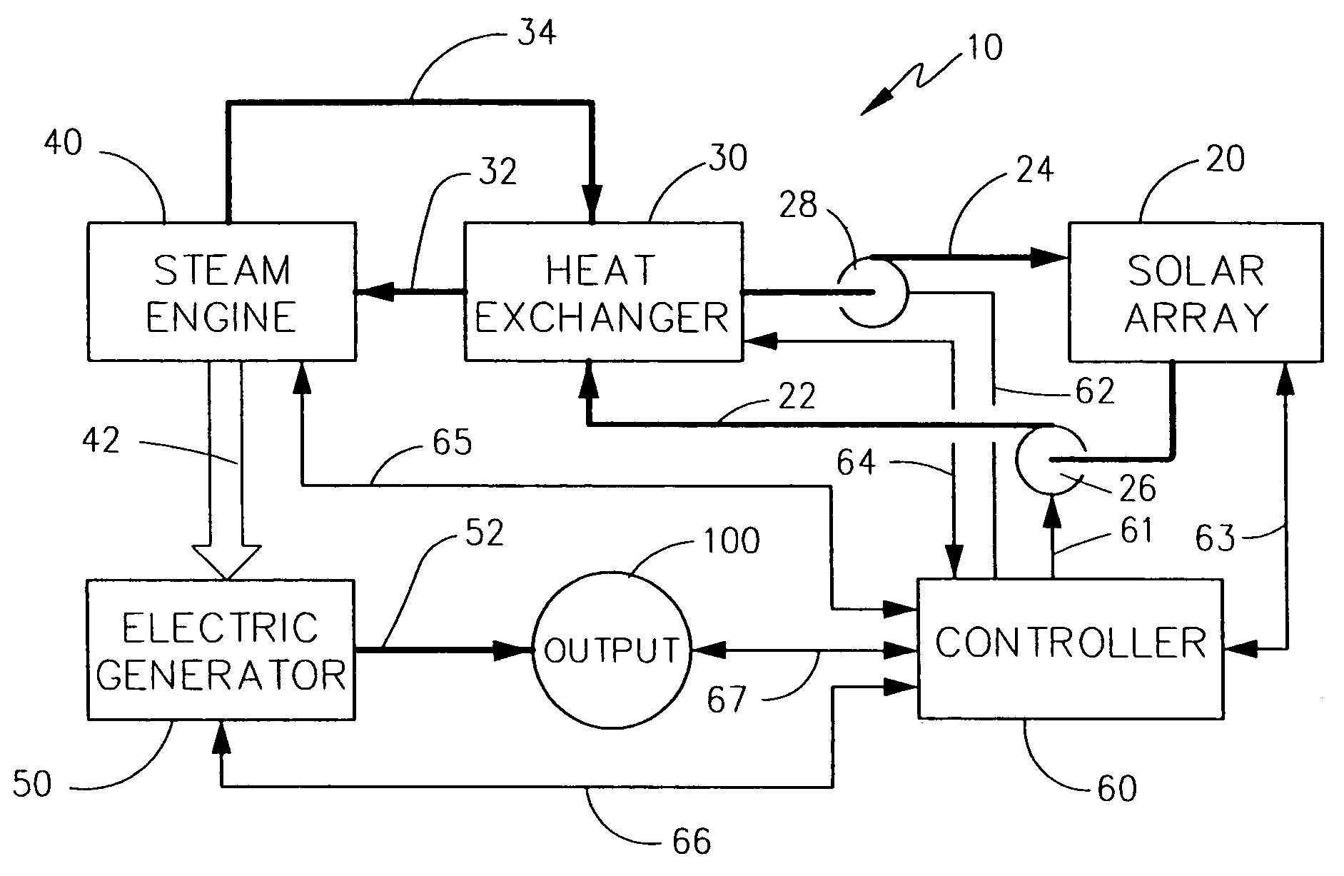
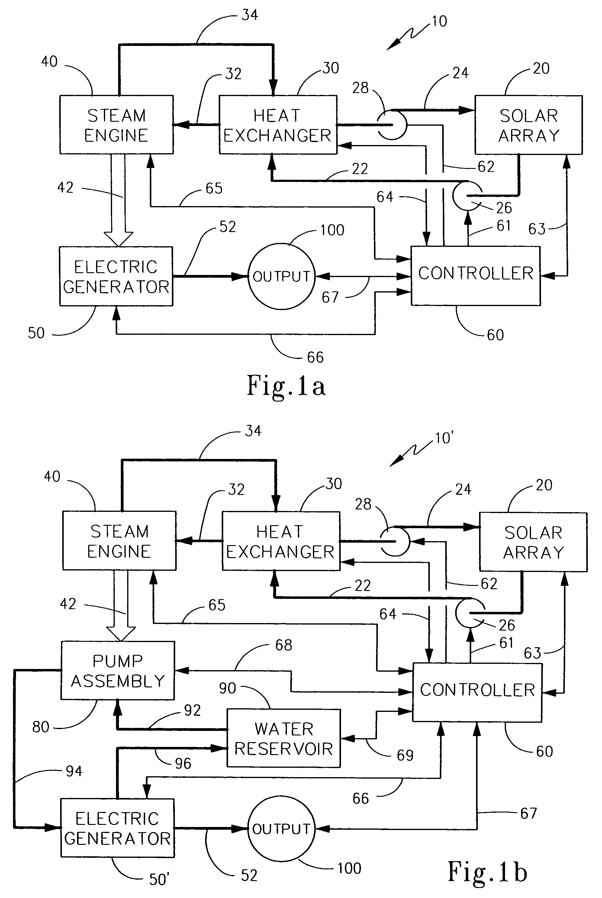
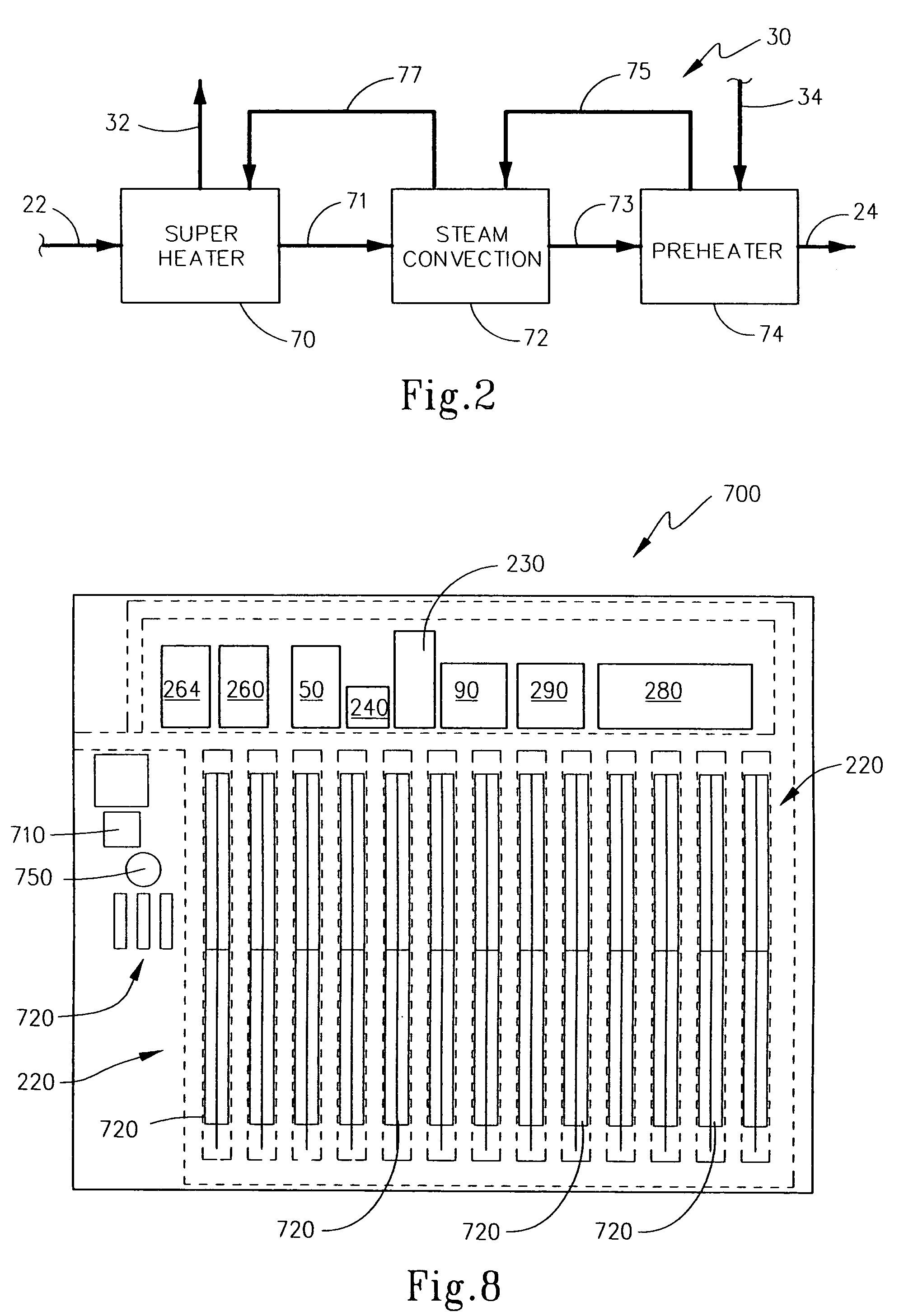
[0044]In order to introduce the electric generation station according to the present invention, reference may be made first to FIGS. 1(a) and 1(b). In FIG. 1(a), a diagram of a simplified electric generation station is illustrated. Here, electric generation station 10 includes a solar array 20 that is provided with a transfer fluid that is adapted to be heated by incident solar radiation, as is known in the art. Solar array 20 is in fluid communication through suit...


PUM


Abstract

An electric generation station employs a solar array to heat a thermal transfer fluid that is supplied to a heat exchanger to produce steam. The heated steam drives a steam engine that operates either an electric generator to produce electricity or a pump assembly. The pump assembly can pump water to an elevated location for use during peak times by flowing water downwardly past an electric generator. The electric generators can be pelton turbines. One or more thermal fluid storage facilities can be used to store heated fluid, and heat may also be stored in a heat retaining material. Additional optional features and combinations of optional assemblies are disclosed. A method of generating electricity with these systems is also described.

Description

FIELD OF THE INVENTION[0001]The present invention broadly relates to energy sources and, in particular, to production facilities for generating electricity. More specifically, the present invention concerns the production of electricity by means of solar power. This invention is also directed to electric generation facilities and methods wherein electricity may ultimately be generated from solar power, but wherein the time of day during which production of such electricity occurs may be selected.BACKGROUND OF THE INVENTION[0002]The very process of life relies upon the presence of a source of energy. This energy ultimately derives from thermonuclear processes occurring in the sun that create energy in the form of electromagnetic radiation in the form of light. This electromagnetic energy may then be converted into other forms of energy by a variety of processes.[0003]For example, such solar energy may cause evaporation of water such that the water vapor is transported from a lower el...

Claims


Application Information

Patent Timeline
Patent Type & Authority Patents(United States)
IPC IPC(8): B60K16/00B60L8/00F03G6/00
CPCF03G6/00Y02E10/46Y02T10/7072
Inventor SCHUBERT, FRANK
Owner POWERSTREAMS
Learn More