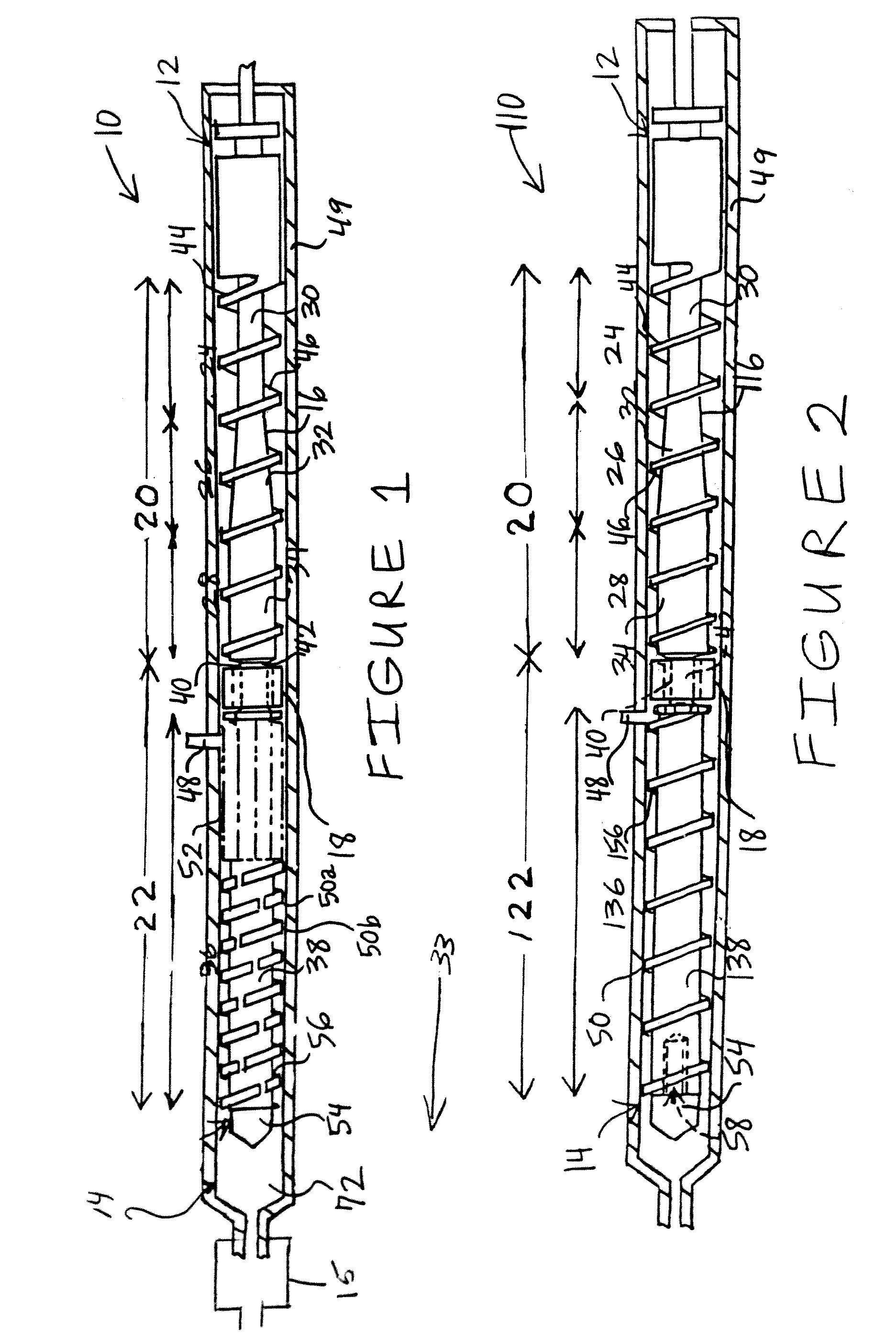
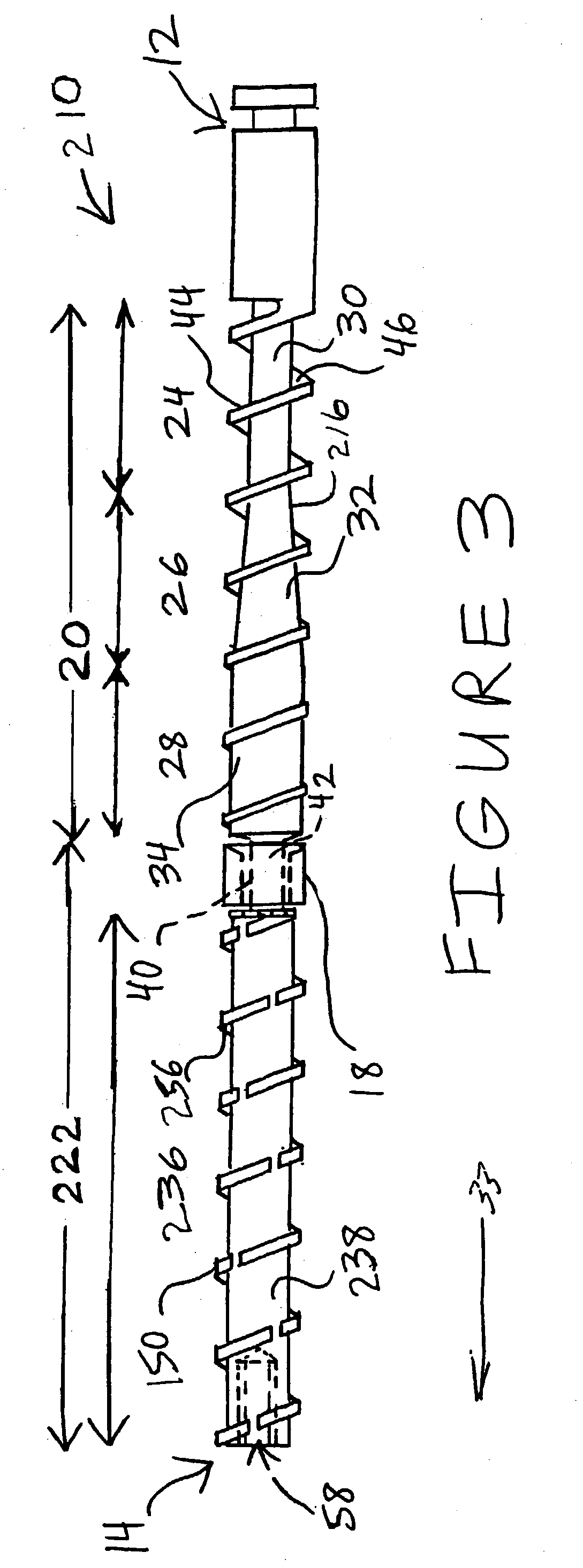
Injection molding screw
a technology of injection molding screw and screw head, which is applied in the direction of mixing/kneading with horizontally mounted tools, manufacturing tools, food shaping, etc., can solve the problems of inconvenient design of injection molding screw used in the mucell® process for metal or ceramic feedstock materials, and the design limitations of the polymer material process, so as to achieve the effect of reducing pressure and reducing pressur
- Summary
- Abstract
- Description
- Claims
- Application Information
AI Technical Summary
Benefits of technology
Problems solved by technology
Method used
Image
Examples
example 1
[0061]The pressure drop of the molten material in the wiping and mixing section of the standard screw for the microcellular process is shown in FIG. 7 with the pressure variation of 2000 PSI during one molding cycle with the PA material tested. The material processed to produce this graph was a 33% short fiberglass reinforced polyamide 6 (Nylon 6) resin. This material was used in processing of polymer MuCell parts with the standard Trexel MuCell screw, and this material was used as a baseline for the process control improvements with the addition of the middle section check ring when processing MIM feedstock materials. This was done initially with polymer materials in an effort to control development costs, as MIM feedstock materials are costly, and ultimately to provide a timely correlation between the standard Trexel screw and the screw of the present invention. The curve with the large peak and valleys is the standard Trexel screw data. FIG. 7A provides an expanded view of data p...
example 2
[0063]The data provided in FIG. 8 show the performance of the screw of the present invention with processing a general-purpose grade of an unfilled polypropylene material. This polymer material is in the same family of resins as polyethylene and polystyrene (olefins) the ingredients used in the AMP and Penn State MIM feedstock materials that are employed to produce microporous metal material. The goal was to determine the pressure decay from a process start-up to a stable process at the mid-section check ring location. The decay was held to about 600 PSI. The processing conditions are provided in Table A.
[0064]
TABLE AMachine Process SettingValueUnitsNote:Barrel Temperature, Zone #1430FahrenheitFeedthroat EndBarrel Temperature, Zone #2440FahrenheitBarrel Temperature, Zone #3440FahrenheitBarrel Temperature, Zone #4440FahrenheitShut-off nozzle, Zone #5440FahrenheitShut-off nozzle endScrew Stroke0.9inch30 mm screwScrew Recovery Speed8.0inch / secondcircumferentialspeedBack Pressure1,500po...
example 3
[0065]The data in FIG. 9 show the pressure variation in processing at the mid-section check location on the screw of the injection molding screw of the present invention. Solid MIM material formulated by Penn State University is being processed (microporous MIM turned OFF). The MIM feedstock check ring location melt pressure variation drop is in alignment with FIGS. 7 and 7A. However, the pressure rise on screw recovery is a result of the lower viscosity of the MIM feedstock material as compared to the 33% glass filled nylon material in FIGS. 7 and 7A. The decay after screw stoppage was almost liner to the point of injection, indicated with the slight drop in pressure before the screw rotation pressure rise. The lack of the pressure decay after screw stoppage and before injection indicates that the mid-section check ring is functioning with the MIM feedstock material. The processing conditions are provided in Table B.
[0066]
TABLE BMachine Process SettingValueUnitsNote:Barrel Temperat...
PUM
| Property | Measurement | Unit |
|---|---|---|
| pressure | aaaaa | aaaaa |
| pressure | aaaaa | aaaaa |
| pressure | aaaaa | aaaaa |
Abstract
Description
Claims
Application Information
 - R&D
- Intellectual Property
- Life Sciences
- Materials
- Tech Scout
- Unparalleled Data Quality
- Higher Quality Content
- 60% Fewer Hallucinations
Browse by: Latest US Patents, China's latest patents, Technical Efficacy Thesaurus, Application Domain, Technology Topic, Popular Technical Reports.
© 2025 PatSnap. All rights reserved.Legal|Privacy policy|Modern Slavery Act Transparency Statement|Sitemap|About US| Contact US: help@patsnap.com


