Printed board and meter unit provided therewith

a technology of meter unit and printed board, which is applied in the association of printed circuit non-printed electric components, electric apparatus casings/cabinets/drawers, instruments, etc., can solve the disadvantageous narrow operation frequency range of electric wave receivers and difficult practicality, and achieve the effect of efficiently reducing the noise of dissipation radiation caused by high frequency signal sources

Inactive Publication Date: 2007-02-06
NIPPON SOKEN +1
View PDF10 Cites 7 Cited by
  • Summary
  • Abstract
  • Description
  • Claims
  • Application Information

AI Technical Summary

Benefits of technology

[0007]The present invention is considered in view of the above circumstance, and the purpose is to provide a printed board that is practical and adequately effective for reducing its noise and a meter unit provided therewith.
[0009]The electrically conductive membrane has the component hole pattern surrounding the high frequency signal source or the mounting component, and the electrically conductive membrane forms a ground connected portion extended not linearly but flatly on the area where the high frequency circuit is formed. Accordingly, the grounded area can be secured more sufficiently than the linear one, and the area where the high frequency circuit serving as a noise source is installed can be grounded more enough. Therefore, even though the electrically conductive membrane is not formed in the area where the high frequency circuit is not installed, the noise is less likely to be conducted to the wiring pattern disposed in the area where the high frequency circuit is not formed, thereby restraining dispensable radiation noise from being generated. Consequently, the noise can be sufficiently effectively reduced similarly to a printed board where the electrically conductive membrane is fully formed. In addition, the electrically insulative membrane and the electrically conductive membrane are formed in a limited area, thereby advancing the practicability.
[0011]The loop-shaped closed ground pattern restrains a magnetic noise more effectively than one in which the ends are not connected. Moreover, the connective ground patterns reduce the ground resistance, thereby restraining the ground patterns serving as an antenna. Accordingly, the noise can be sufficiently effectively reduced similar to one having a board in which the electrically conducive membrane is fully formed. In addition, the pattern can be formed not to be flatly extended but to be linearly extended, thereby simplifying the structure and advancing the practicability.
[0013]Accordingly, a dispensable radiation noise caused by the high frequency signal source can be efficiently reduced.

Problems solved by technology

Accordingly, the keyless entry system is erroneously operated, and the operational frequency range of the electric wave receiver is disadvantageously narrowed.
Therefore, this is hard to be practical.

Method used


Image

  • Printed board and meter unit provided therewith
  • Printed board and meter unit provided therewith
  • Printed board and meter unit provided therewith

Examples


first embodiment

(First Embodiment)

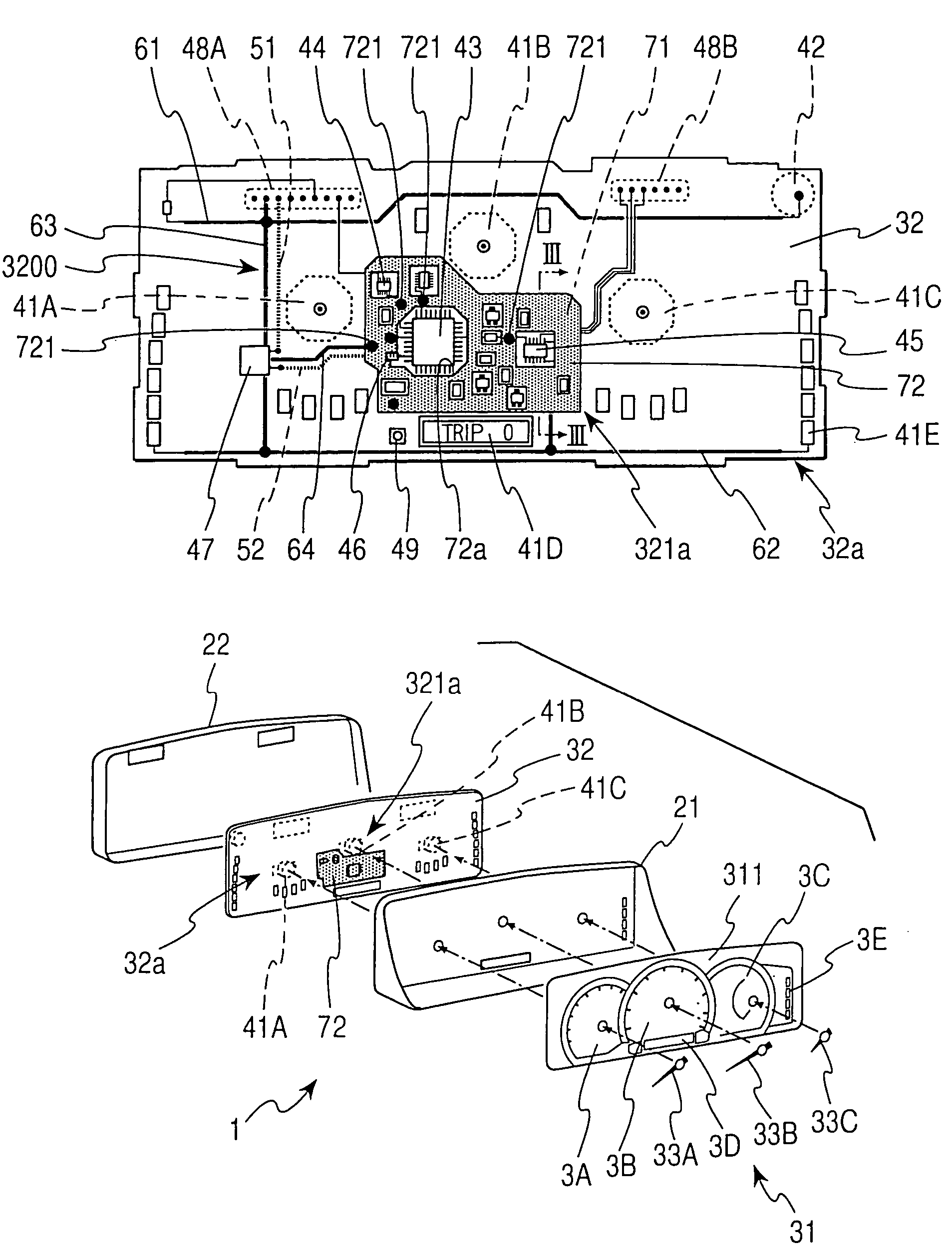
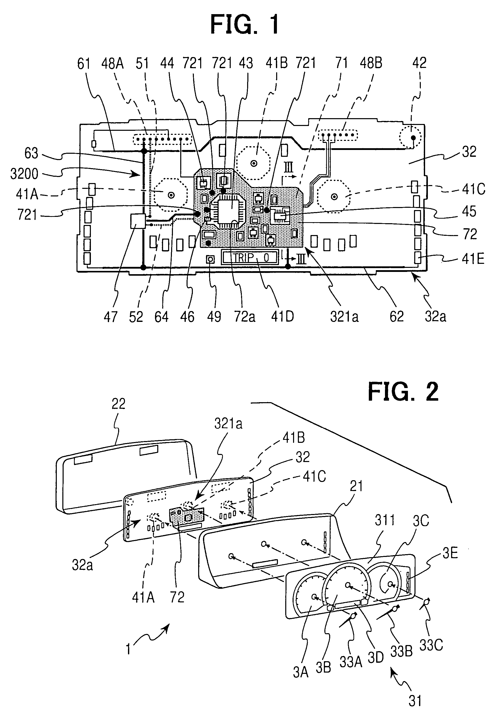
[0025]As shown in FIG. 2, the meter unit 1 is provided with -an upper housing 21 to be fitted into an instrument panel of a passenger compartment and a lower housing 22. An indicative portion 31 is attached to the upper housing 21 on its passenger side. A transparent clear housing (not shown) is disposed in front of the indicative portion 31 and covers the indicative portion 31 in front thereof. Meter devices, such as meters 3A, 3B, 3C, 3D, are arranged in the indicative portion 31 and indicate driving information or the like of a vehicle for a passenger of the vehicle. Over the back side of an indicative board 311 of the indicative portion 31, the side being on the opposite side as a passenger, a printed board 32 is installed.

[0026]As shown in FIG. 1, with respect to arrangement of the meters 3A–3D, a speed meter 3B is disposed in the substantial center, a tachometer 3A is disposed on the left thereof, and a little smaller fuel meter 3C is disposed on the right. M...

second embodiment

(Second Embodiment)

[0040]A printed board according to the second embodiment will be described with reference to FIG. 6. The basic structure of a meter unit is the same as that according to the first embodiment, and differences between the first and second embodiments will be particularly described.

[0041]In a printed board 32A, one end portion on the side of the CPU 43 of an electricity supply line 52A, through which electricity is supplied from the CPU 43 to the electric regulator 47, forms an electrically conductive membrane 73 on the electrically insulative membrane 71 covering the board (hereinafter, according to need, the electrically conductive membrane 73 of the electricity supply line 52A in the vicinity of the CPU 43 is referred to as a paste electricity supply line 73, and the electrically conductive membrane 72 is referred to as a paste ground 72). The paste electricity supply line 73 is positioned inside a component hole pattern 72a of the paste ground 72 and disposed in ...

third embodiment

(Third Embodiment)

[0043]The third embodiment of the present invention will be described with reference to FIGS. 7, 8 and 9. The basic structure of a meter unit is the same as that of the first embodiment, and the differences between the first embodiment and the third embodiment will be particularly described.

[0044]The shape of a ground line 65 of a printed board 32B is different from that of the ground lines 61, 62 shown in FIG. 1, the ends of which are not connected. The shape of a ground line 65 is a continuous rectangular closed loop-shape, in which the ground lines 65 are extended along the edge of the printed board 32. The loop-shaped ground line 65 is connected with a ground terminal of a battery regulator 47 and a ground terminal of a connector 48A for supplying electricity.

[0045]Moreover, in this embodiment, as ground lines, ground lines 66 (hereinafter, according to need, referred to as a reinforcing groundlines) are formed. The ground line 66 is, for example, disposed insi...


PUM


Abstract

A printed board has a board, an electrically insulative membrane, formed on the board, and an electrically conductive membrane, formed on the electrically insulative membrane, in its area where a control circuit, including a CPU and etc., is installed. The electrically conductive membrane is electrically connected with ground patterns of a wiring pattern. Accordingly, ground connections at the control circuit are sufficiently performed. Therefore, even though ground connections in an area other than the control circuit are not sufficiently performed, a magnetic noise is prevented from being generated in a loop-shaped electricity supply line passing through a CPU and etc. Consequently, noises in printed board can be effectively reduced.

Description

CROSS REFERENCE TO RELATED APPLICATION[0001]This application is based on Japanese Patent Application No. 2002-348517 filed on Nov. 29, 2002, the disclosure of which is incorporated herein by reference.FIELD OF THE INVENTION[0002]The present invention relates to a printed board and a meter unit provided therewith, and more particularly relates to the structure thereof for reducing a generated noise.BACKGROUND OF THE INVENTION[0003]Recently, an automobile is provided with an electric wave receiving device other than a car radio, e.g., an electric wave receiving device for a keyless entry system. The keyless entry system is a control device for opening or closing a door of a vehicle and includes a keyless entry receiver installed inside the vehicle and a keyless entry transmitter installed inside a key, etc. The keyless entry transmitter transmits a signal with an ID code associated with the transmitter and a modulated operational command code, when operated. When the keyless entry rec...

Claims


Application Information

Patent Timeline
Patent Type & Authority Patents(United States)
IPC IPC(8): H05K7/02H05K7/06H05K7/08H05K7/10G01D11/24B60K35/00H05K1/02H05K9/00
CPCH05K1/0218B60K2350/302B60K2370/42H05K1/02
Inventor SUGIMOTO, YUJIKOUNO, SYUICHIMIYAGAWA, TOMOYUKI
Owner NIPPON SOKEN
Why Eureka
Try Eureka