System and method for leak detection

a leak detection and system technology, applied in the direction of measurement devices, structural/machine measurement, instruments, etc., can solve the problems of contaminating the product within the barrier isolator chamber, difficulty, and hazardous exposure of operators, so as to facilitate the leak testing process, and minimize the duration of the leak test cycle

Inactive Publication Date: 2007-02-13
SACCA GIUSEPPE
View PDF29 Cites 34 Cited by
  • Summary
  • Abstract
  • Description
  • Claims
  • Application Information

AI Technical Summary

Benefits of technology

[0024]In a more narrow aspect, the flow controller assembly further includes a high flow valve for applying an initial fluidic pressure to tiie test part at a higher flow rate than the selected relatively constant flow rate prior to the application of a fluldic pressure to the test part at the selected flow rate. The control system adjusts the relatively higher flow rate for a first programmed time duration to maintain the fluidic pressure to the test part at or above a predetermined threshold pressure also prior to the step of applying a fluidic pressure to the test part at the selected relatively constant flow rate. Further, the control system applies the selected relatively constant flow rate for a second programmed time duration before comparing the fluidic pressure with the predetermined threshold pressure wherein the fluidic pressure being greater than the predetermined threshold pressure is indicative of a leak free test part and wherein the fluidic pressure being lower than the threshold pressure is indicative of a leak in the test part. This methodology of using the predetermined threshold pressure as the indicator of a passing or a failing leak test has the advantage of subjecting the test part to a given test pressure level while injecting a constant flow rate. As a result, it is possible to approximate a stable and repeatable test part condition, meaning consistent amount of stretch, at the time that the pass / fail determination is made. This is particularly of importance when testing a rubber-like component, such as a rubber glove.
[0025]In an alternate embodiment, the flow controller assembly includes a high flow valve as discussed above; however, the system utilizes a positive pressure trend with the fluidic pressure being greater than the predetermined threshold pressure as indicative of a leak free test part and a negative pressure trend with the fluidic pressure being lower than the predetermined threshold pressure as indicative of a leak in the test part. This method of interpreting the leak test conditions adds the benefit of minimizing the leak test cycle duration by allowing its determination to be based on conditions rather than time duration.

Problems solved by technology

In recent years, in the pharmaceutical industry, because of the expense and operational difficulties of maintaining so-called “clean rooms” into which operators enter to carry out procedures, the use of isolation barriers has become common practice.
In the case of an aseptic operation, the operator's hand that is by definition “dirty” can come into contact with the breach thus creating the possibility of contaminating the product within the barrier isolator chamber.
In the case of containment applications, the breach can allow the compound being contained within the barrier isolator to escape with a resulting hazardous exposure to the operator.
Such technology would encounter difficulties in its adoption for testing gloves because of the rubber material of the glove and the inherent unpredictable physical behavior of the material itself.
The rubber material of the glove does not permit the use of physical characteristics to determine test part integrity.
Although reliable and widely used, this technology has the inherent limitation that the detection of a breach is ultimately left up to the visual observation by the operator, with the related human factor reliability limitations.
In addition, the use of a fluid in a production environment can be operationally limiting and unfriendly.
If this measured flow rate is higher than some predetermined value, the part under test is deemed to be defective.
It is much more difficult to apply this technology to the testing of rubber components, such as barrier isolator gloves.
The stretching and eventual creep that goes on in a rubber device once positive or negative pressure is applied to its surfaces make achieving a precise reference pressure very time consuming.
This causes an error in the pressure value that is not related to the leak testing process.

Method used


Image

  • System and method for leak detection
  • System and method for leak detection
  • System and method for leak detection

Examples


Embodiment Construction

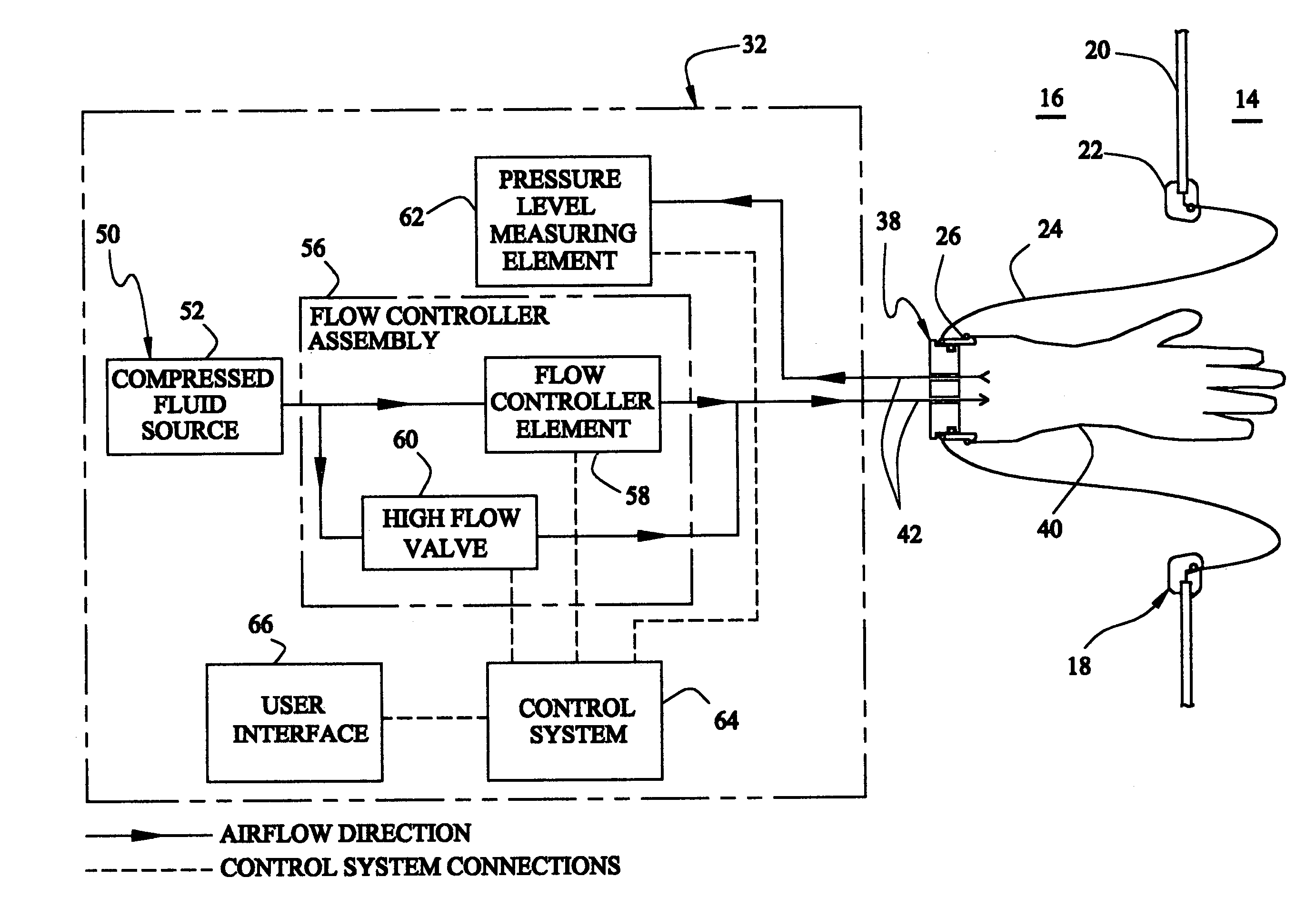
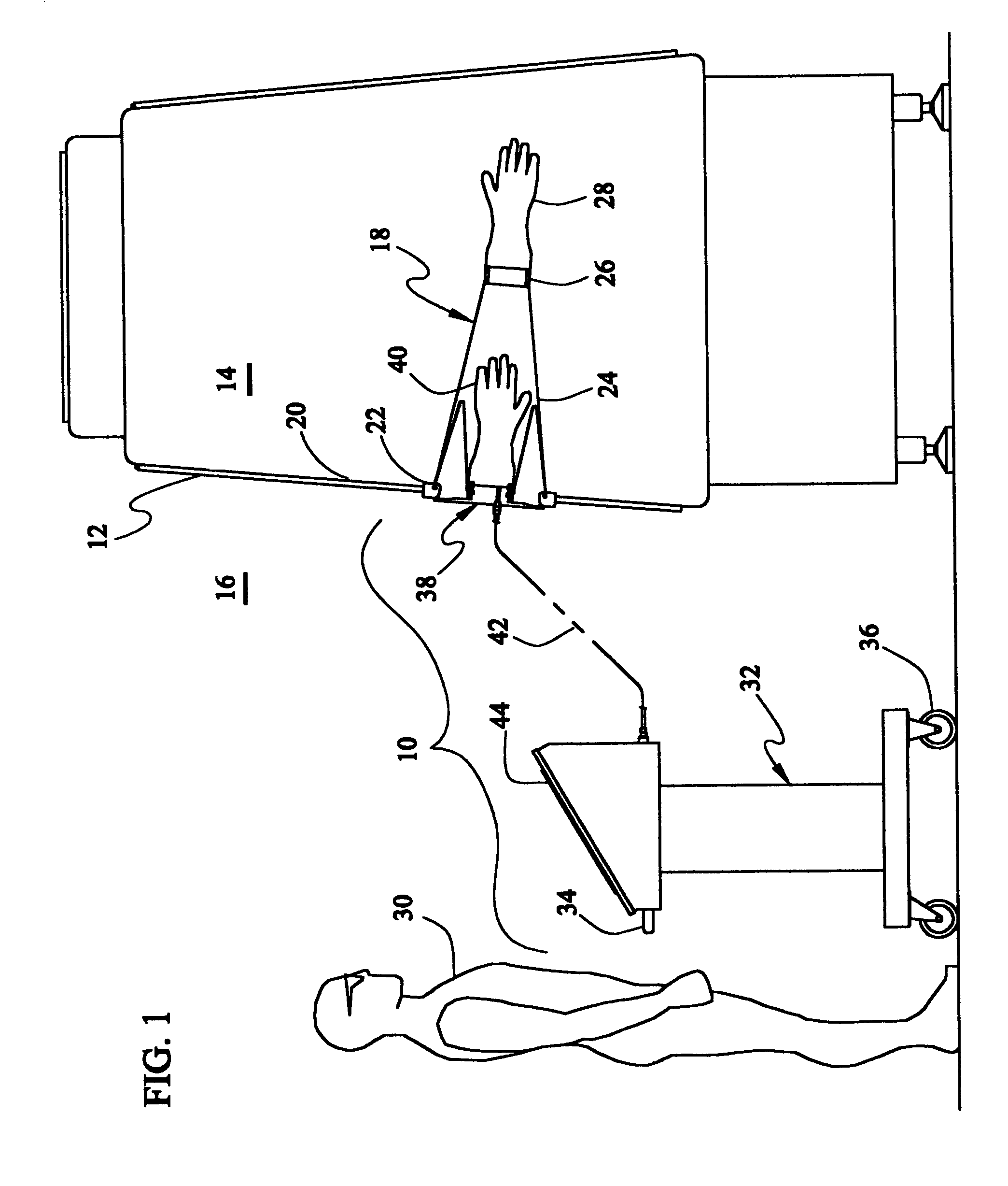
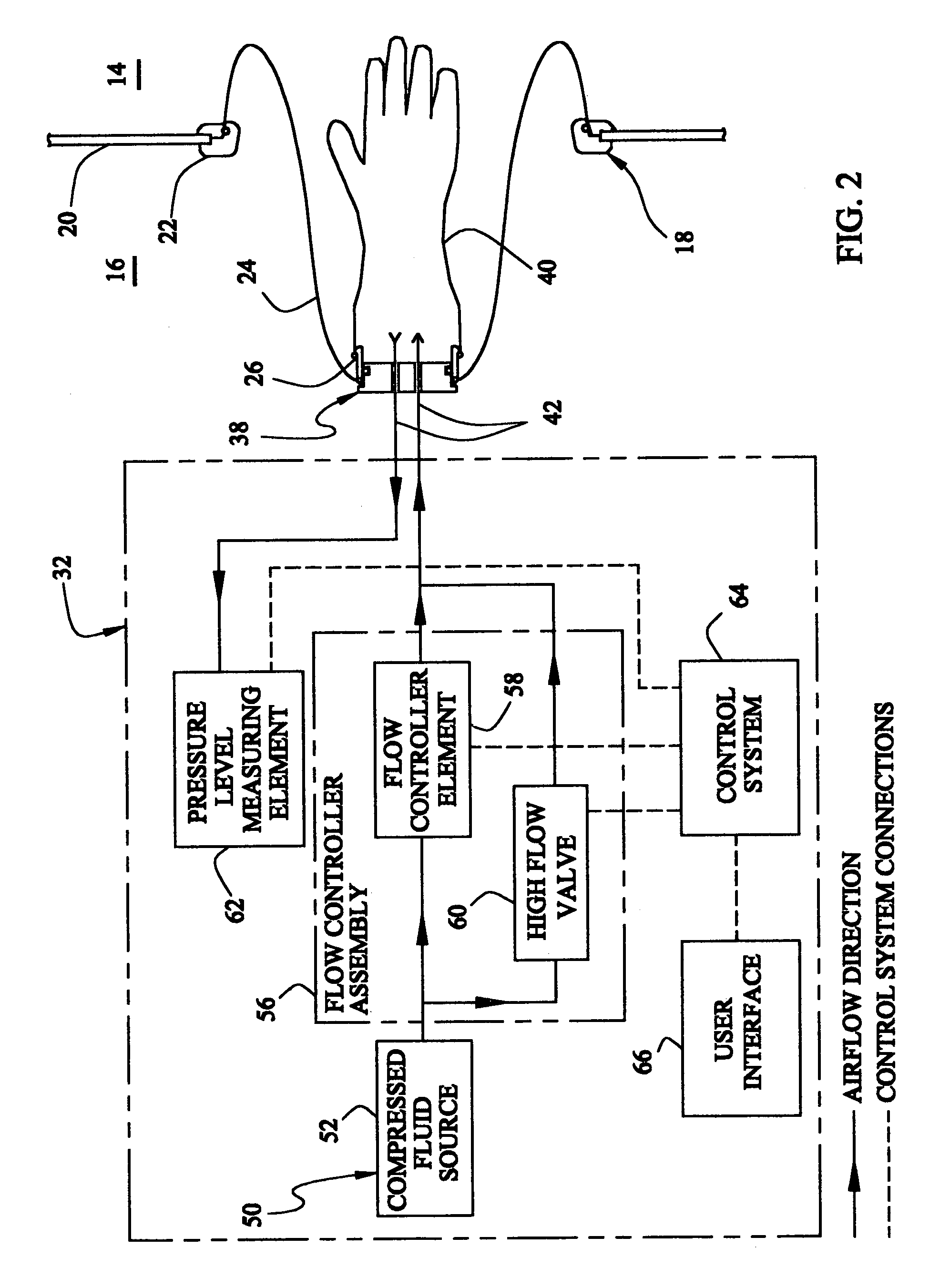
[0037]Referring to the drawings and the characters of reference marked thereon, FIG. 1 illustrates a preferred embodiment of the leak testing system of the present invention, designated generally as 10, shown in use in a normal positive pressure operating environment. The operating environment includes a barrier isolator 12 that creates a sterile environment 14 within a non-sterile filling room 16. To permit access to the sterile environment 14 of the barrier isolator 12, a gloveport system 18 is attached in sealing fashion to the barrier isolator wall 20 of barrier isolator 12. In this particular embodiment, gloveport system 18 includes a gloveport 22, sleeve 24, cuff 26 and glove 28. During normal use, the gloveport system 18 is oriented to the inside of the barrier isolator 12 within the sterile environment 14.

[0038]The leak testing system 10 includes a leak testing control assembly, designated generally as 32; and, a test part interface, designated generally as 38. During use, a...


PUM


Abstract

A leak testing control assembly for a leak testing system of a type that cooperates with a test part interface that is coupled with a test part. In a broad aspect the leak testing control assembly includes a working fluid generator for applying a working fluid having a fluidic pressure to a test part. A flow controller assembly is coupled to the working fluid generator. The flow controller assembly includes a flow controller element for controlling the flow rate of the working fluid. A pressure level measuring element is positioned relative to the test part for measuring the fluidic pressure. A control system is coupled to the flow controller assembly and the pressure level measuring element. A user interface is coupled to the control system for providing user interaction with the leak testing control assembly. During operation, the control system 1) facilitates application of the fluidic pressure at a selected relatively constant flow rate; and, 2) interprets the value of the fluidic pressure, after the application of the fluidic pressure at the selected relatively constant flow rate, to determine whether the test part is free of leaks.

Description

BACKGROUND OF THE INVENTION[0001]1. Field of the Invention[0002]This invention relates to leak detection systems and more particularly to leak detection systems for gloves utilized with isolator barrier systems.[0003]2. Description of the Related Art[0004]Certain manufacturing processes require the maintenance of separation between two environments to avoid contamination of the cleaner of the two environments by the dirtier of the two. This is accomplished with the use of environments, such as isolation barriers also commonly known as gloveboxes or simply isolators. For example, in the case of certain pharmaceutical products, the manufacturing process is perfomied within these isolation barriers to prevent contamination of the product being produced by dust particles, bacteria and viruses that are found in the outside ambient air. This type of application is commonly referred to as an aseptic application of isolation barriers. The same holds true for the assembly of certain medical ...

Claims


Application Information

Patent Timeline
Patent Type & Authority Patents(United States)
IPC IPC(8): G01M3/04
CPCG01M3/3218G01M3/3281G01M3/3236
Inventor SACCA, GIUSEPPE
Owner SACCA GIUSEPPE
Why Eureka
Try Eureka