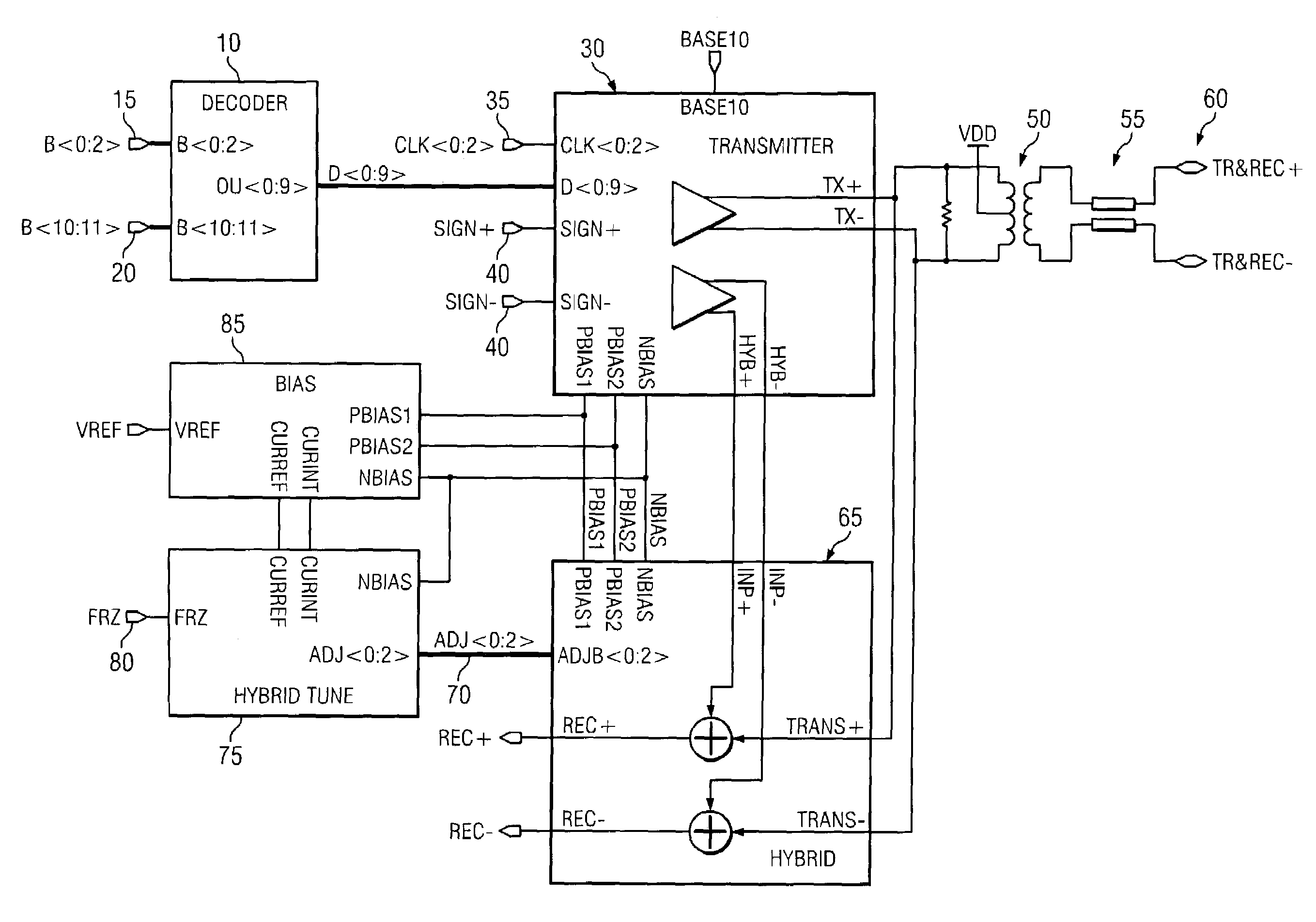
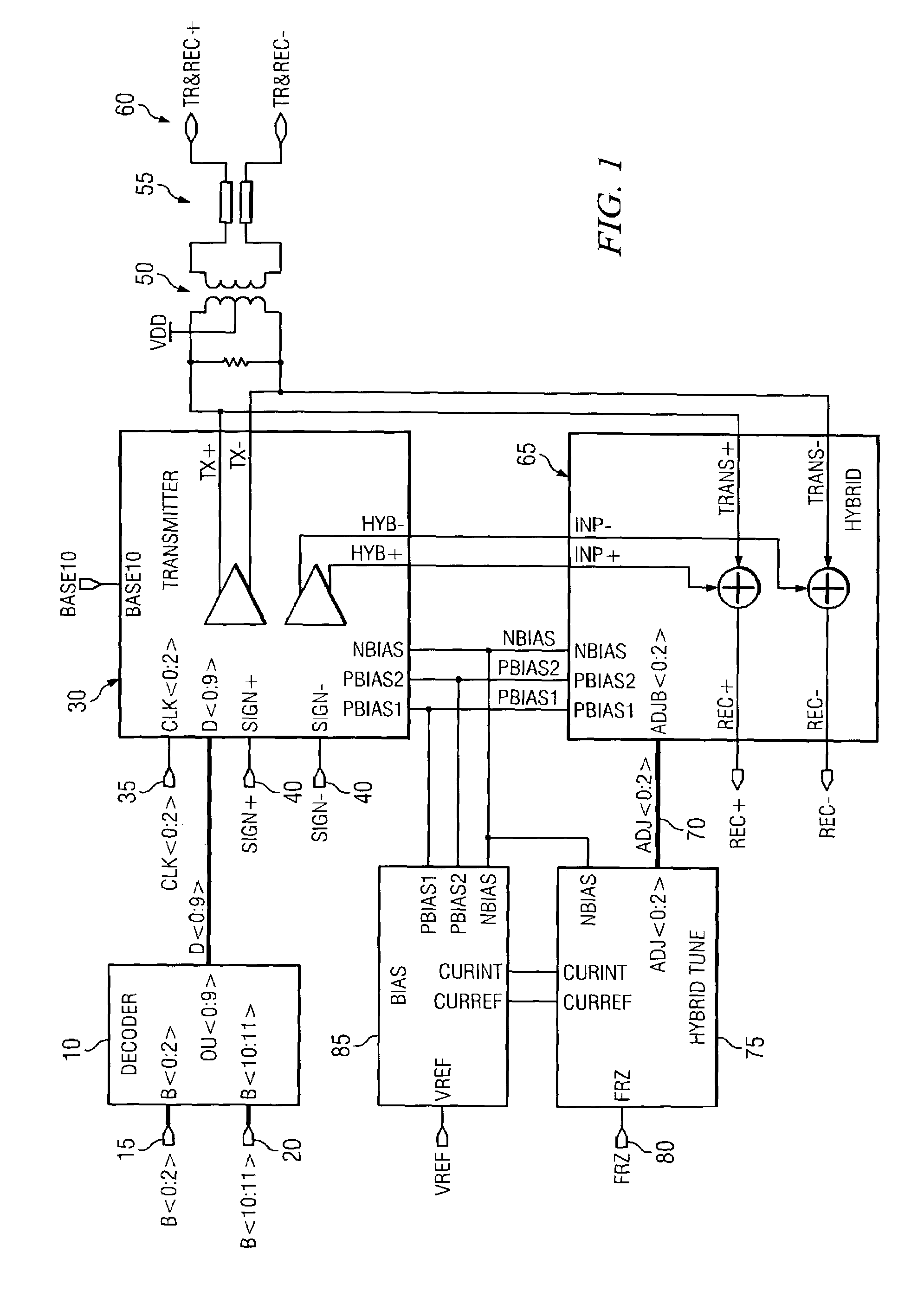
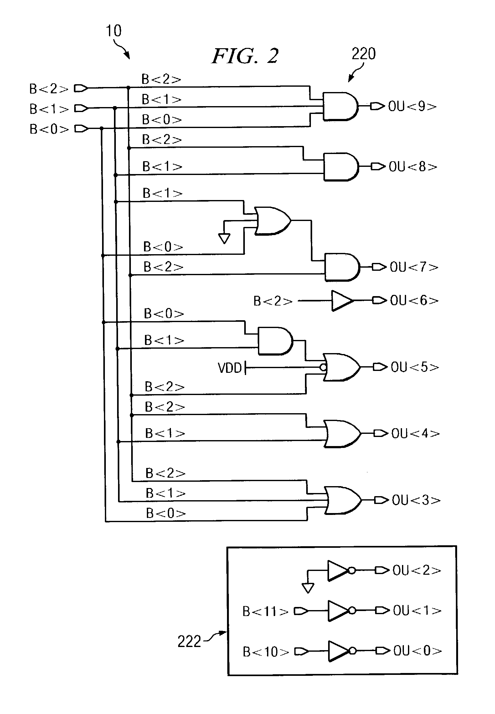
Gigabit ethernet line driver and hybrid architecture
a hybrid architecture and ethernet line technology, applied in the field of ethernets, can solve the problems of large capacitance of driver output filter, inconvenient placement in the transceiver chip, and inability to meet the needs of baseband system details, etc., and achieve the effect of avoiding the leakage of transmission signal distortion into the receive path, reducing the efficiency of transmission signal, and reducing the cost of transmission
- Summary
- Abstract
- Description
- Claims
- Application Information
AI Technical Summary
Benefits of technology
Problems solved by technology
Method used
Image
Examples
first embodiment
[0041]The schematic of the comparator 275 used for the hybrid 65 (FIG. 8) is shown in FIG. 15. The comparator 275 contains a replica of the hybrid resistor string 305 with switches 310 connected to the resistor taps. The switches 310 are controlled by a decoder 315 similar to decoder 240 (FIG. 9). The selected switch applies a process independent current generated by current mirror 320 to the respective part of the resistor string 305. A process dependent current generated by current mirror 335 is applied to resistor 315 to create a reference voltage drop across the resistor. Transconductor cell 330 converts the voltage difference between the reference resistor 315 and the resistor string 305 in its output current applied to the current comparator 342. The limits of the comparator are set by current sources 340a and 340b. If the transconductor current exceeds the limit, either “GOUP” or “GODOWN” goes “HIGH”.
second embodiment
[0042]The schematic of the comparator 275 used for the hybrid 65 (FIG. 10) is shown in FIG. 16. The comparator 275 contains a replica 350 of a hybrid cell. The replica 350 (presents the slave side) and master transistor 355 composes a current mirror, which receives a reference process independent current “CURREF”. A process dependent current “CURRINT” is applied to the drain node of replica 350. Tile current difference is applied to current comparator 360, which was described above.
[0043]The bias generator 85 circuit diagram is shown in FIG. 17. The bias generator 85 contains two similar portions: portion 400, which is responsible for generation of the process independent reference voltages and currents; and portion 405 responsible for generation of the process dependent current. They contain external precise resistor 410, connected to an n external pin of the chip, and internal process dependent resistor 415. Each portion 400, 405 contains an operational amplifier 420 connected in ...
PUM
 Abstract
Description
Claims
Application Information
 - R&D
- Intellectual Property
- Life Sciences
- Materials
- Tech Scout
- Unparalleled Data Quality
- Higher Quality Content
- 60% Fewer Hallucinations
Browse by: Latest US Patents, China's latest patents, Technical Efficacy Thesaurus, Application Domain, Technology Topic, Popular Technical Reports.
© 2025 PatSnap. All rights reserved.Legal|Privacy policy|Modern Slavery Act Transparency Statement|Sitemap|About US| Contact US: help@patsnap.com


