
Preamplifier circuit with signal interference cancellation suitable for use in magnetic storage devices

a preamplifier circuit and signal interference technology, which is applied in the field of preamplifier circuits, can solve the problems of affecting the accuracy of the signals being read from the disk, undetectable influence on the spectral content of the read signal, and too much interference may be picked up, so as to achieve accurate cancellation of interference signals.

Inactive Publication Date: 2007-02-13
HITACHI GLOBAL STORAGE TECH NETHERLANDS BV
View PDF10 Cites 2 Cited by
  • Summary
  • Abstract
  • Description
  • Claims
  • Application Information

AI Technical Summary

Benefits of technology

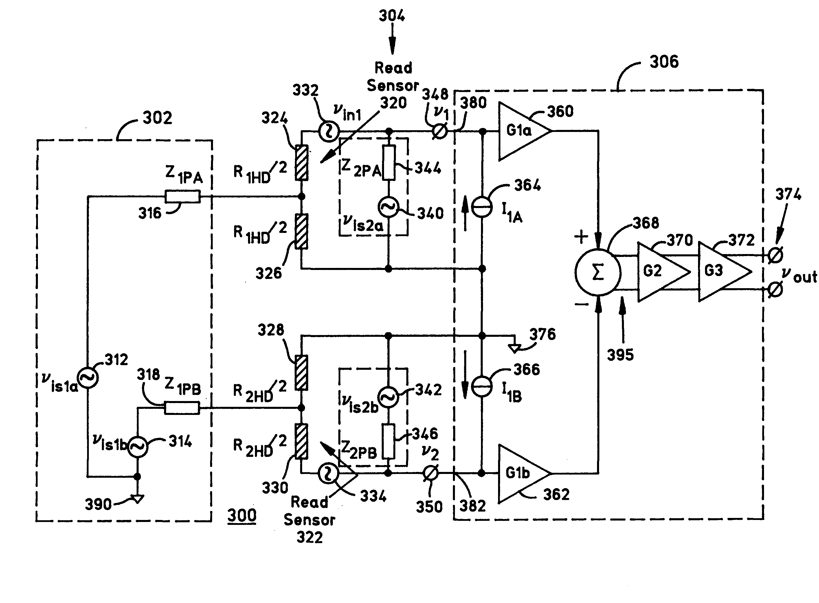
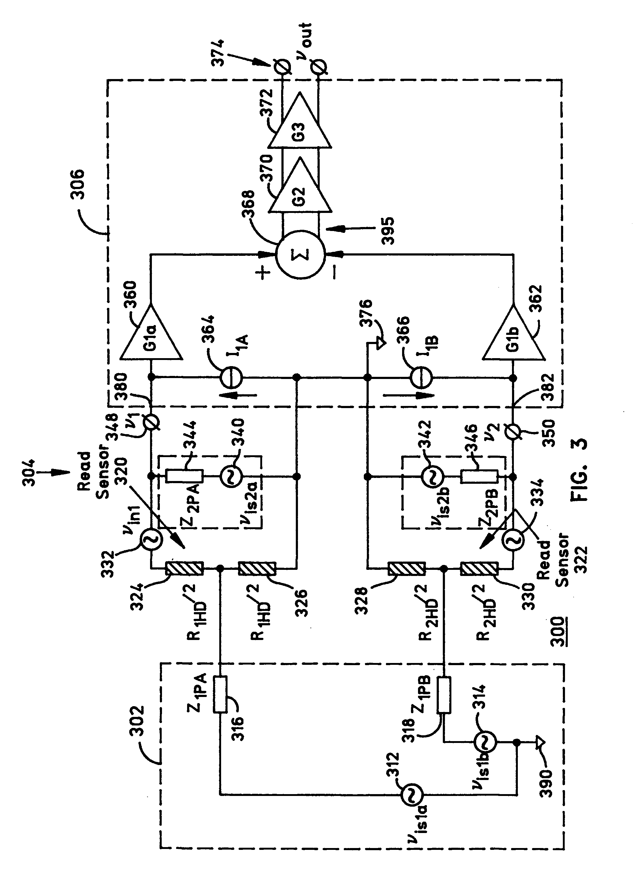
"The patent describes a magnetic storage device with a magnetic head and a suspension system. The device also includes read circuitry with a preamplifier and a subtractor. The preamplifier has two input ports and two current / voltage bias sources for actively biasing and zero biasing the read sensors. The subtractor has two inputs, one with the read sensor data signal and interference signal, and the other with just the interference signal. The output of the subtractor provides a read sensor signal without the interference signal. The gain of the amplifier in the preamplifier circuit can be adjusted to accurately cancel out the interference signal despite any mismatches in component values. The technical effect of this invention is to improve the accuracy and reliability of magnetic storage devices by reducing interference signals and improving the read sensor signal-to-noise ratio."

Problems solved by technology

Unfortunately, without appropriate preamplifier circuitry in the read circuitry, too much interference may be picked up while reading the signals from the read sensor to the input of the read amplifier.
The preamplifier circuitry typically amplifies low-level differential-mode readback data signals along with undesirable common-mode interference signals.
Such interference ultimately affects the accuracy of the signals being read from the disk.
Finally, transmission line interference-coupling effects of the suspension interconnect, during high data rate operation, may undesirably influence the spectral content of the read signal.
For one, they consume a relatively large amount of power.
Finally, due to “floating inputs” (i.e. controlled near-ground potential), the front-end circuit has a relatively long transient recovery time.

Method used


Image

  • Preamplifier circuit with signal interference cancellation suitable for use in magnetic storage devices
  • Preamplifier circuit with signal interference cancellation suitable for use in magnetic storage devices
  • Preamplifier circuit with signal interference cancellation suitable for use in magnetic storage devices

Examples


Embodiment Construction

[0016]The present invention described herein significantly reduces common-mode interference signals for single-ended multiple-input port preamplifiers. Singled-ended preamplifiers typically amplify common-mode interference signals along with low-level differential-mode signals from transducers. The interference signals can create errors in subsequent data processing. The present invention helps to reduce if not eliminate such errors in the subsequent processing.

[0017]Broadly, a multiple-input port preamplifier has a selected input port which is used to sense both a magnetic disk signal and a common-mode interference signal, and an unselected read port which is used to sense only the common-mode interference signal. Unselected input ports of the multiple-input port preamplifier will not have the transducer bias activated (i.e. it is zero-biased) and therefore will not be able to sense the magnetic disk signal. However, the unselected read port is still able to sense the common-mode i...


PUM

PropertyMeasurementUnit
voltage biasaaaaaaaaaa
current/voltage biasaaaaaaaaaa
voltageaaaaaaaaaa

Abstract

In one illustrative example disclosed, a magnetic storage device includes at least one magnetic disk; a magnetic head which includes first and second read sensors; a suspension which supports the magnetic head relative to the magnetic disk; and read circuitry which includes a preamplifier. The preamplifier has a first input port coupled to the first read sensor; a second input port coupled to the second read sensor; a first bias source coupled to the first input port for actively current / voltage biasing the first read sensor; a second bias source coupled to the second input port for zero biasing the second read sensor; and a subtractor having first and second inputs coupled to the first and the second input ports, respectively. The first input of the subtractor is provided with a first signal which includes a read sensor data signal and an interference signal, whereas the second input of the subtractor is provided with a second signal which includes the interference signal but not the read sensor data signal. Thus, an output of the subtractor provides a read sensor signal without the interference signal.

Description

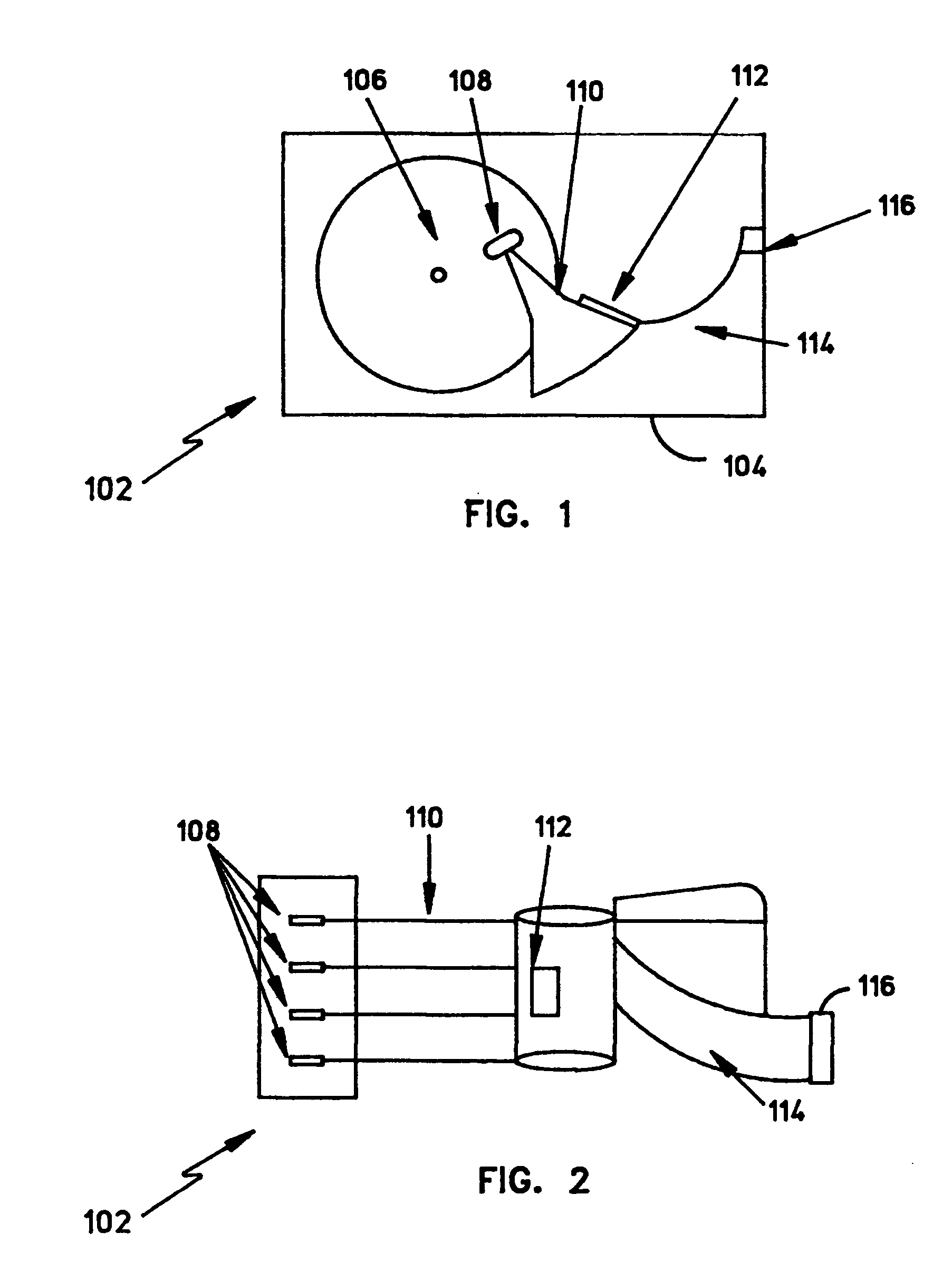
BACKGROUND OF THE INVENTION[0001]1. Field of the Invention[0002]The present invention relates generally to preamplifier circuits, and more particularly to preamplifier circuitry with signal interference cancellation suitable for use in magnetic storage devices.[0003]2. Description of the Related Art[0004]A magnetic storage device (such as a disk drive) typically includes a magnetic disk, a spindle motor which spins the magnetic disk, a magnetic head which has one or more read sensors, a read / write integrated circuit (R / W IC), and a suspension interconnect coupled between the read sensor and the R / W IC. The read sensor, such as a magnetoresistive (MR) sensor or a giant magnetoresistive (GMR) sensor, for example, is used for reading data from the disk. The read sensor is coupled to an input of the R / W IC, which generally includes read signal processing circuitry. The read signal processing circuitry biases the read sensor with a fixed direct current (DC) bias voltage or current, ampli...

Claims


Application Information

Patent Timeline
Patent Type & Authority Patents(United States)
IPC IPC(8): G11B5/02G11B5/09G11B5/00G11B5/012G11B20/10G11B20/22
CPCG11B5/012G11B20/10009G11B20/22G11B2005/0016G11B2005/0013
Inventor CONTRERAS, JOHN THOMASKLAASSEN, KLAAS BERENDVAN PEPPEN, JACOBUS CORNELIS LEONARDUS
Owner HITACHI GLOBAL STORAGE TECH NETHERLANDS BV
Learn More