Optical spectral power monitors employing time-division-multiplexing detection schemes

a detection scheme and spectral power monitor technology, applied in the direction of optical radiation measurement, instruments, spectrometry/spectrophotometry/monochromators, etc., can solve the problems of unsuitable optical networking applications, cumbersome size and operation, and high cost of spectral power monitors, so as to enhance spectral resolution, simple and cost-effective, and great versatility

Inactive Publication Date: 2007-02-13
CAPELLA PHOTONICS INC
View PDF14 Cites 35 Cited by
  • Summary
  • Abstract
  • Description
  • Claims
  • Application Information

AI Technical Summary

Benefits of technology

[0009]The optical spectral power monitoring apparatus of the present invention may further employ a polarization diversity scheme, so as to overcome polarization-sensitive effects the constituent optical elements may possess. In this case, a polarization-separating element and a polarization-rotating element may be disposed along the optical path between the input port and the wavelength-disperser, serving to decompose the input multi-wavelength optical signal into first and second polarization components and subsequently rotate the polarization of the second polarization component by 90-degrees. The wavelength-disperser separates the incident optical signals by wavelength into first and second sets of optical beams, respectively. A beam-focuser (e.g., a focusing lens) may focus the first and second sets of optical beams into corresponding focused spots, impinging onto the beam-manipulating elements. The first and second optical beams associated with the same wavelength may impinge onto (and be manipulated by) the same beam-manipulating element. By operating the beam-manipulating elements according to a desired time-division-multiplexed scheme, the first and second optical beams associated with each wavelength may be successively directed into the optical detector, whereby an optical power spectrum of the input multi-wavelength optical signal can be derived. Alternatively, the first and second sets of optical beams may be directed respectively into first and second optical detectors in a manner that causes the optical beams in each set to arrive at the corresponding optical detector in a time-division-multiplexed sequence. This enables an optical power spectrum associated with each polarization component in the input multi-wavelength optical signal to be separately derived, which would be desirable in WDM optical networking applications.
[0012]By advantageously utilizing an array of beam-manipulating elements that correspond with multiple spectral channels on an individual basis, optical spectral power sensing can be performed in a variety of time-division-multiplexed schemes according to the present invention. This renders greater versatility to the optical spectral power monitoring apparatus thus constructed, in distinct contrast with prior spectral power monitors. Furthermore, the aforementioned polarization diversity scheme renders polarization-sensitive effects inconsequential in the optical spectral power monitoring apparatus of the present invention. This enables the apparatus of the present invention to enhance spectral resolution in a simple and cost-effective construction (e.g., by making use of high-dispersion diffraction gratings commonly available in the art), while providing improved accuracy in optical spectral power detection. Accordingly, a new line of optical spectral power monitors can be constructed according to the present invention, suitable for a variety of applications.

Problems solved by technology

These prior spectral power monitors are typically high in cost, cumbersome in size and operation, and in some instances require considerable maintenance, rendering them unsuitable for optical networking applications.

Method used


Image

  • Optical spectral power monitors employing time-division-multiplexing detection schemes
  • Optical spectral power monitors employing time-division-multiplexing detection schemes
  • Optical spectral power monitors employing time-division-multiplexing detection schemes

Examples


first embodiment

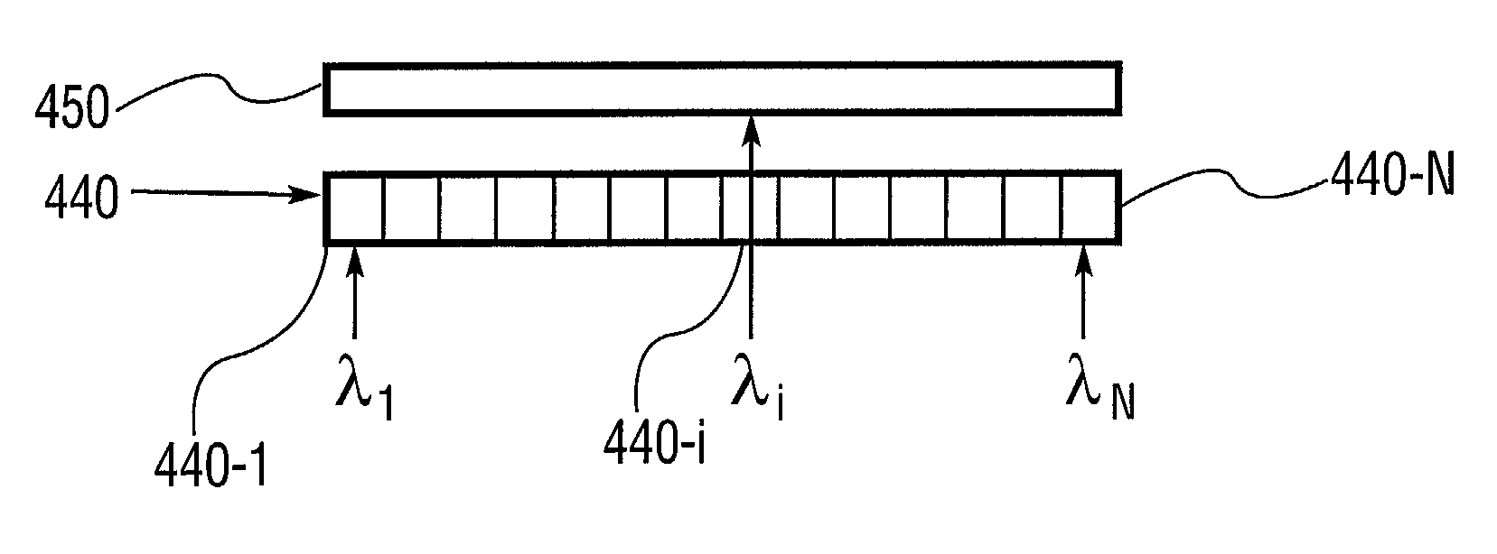
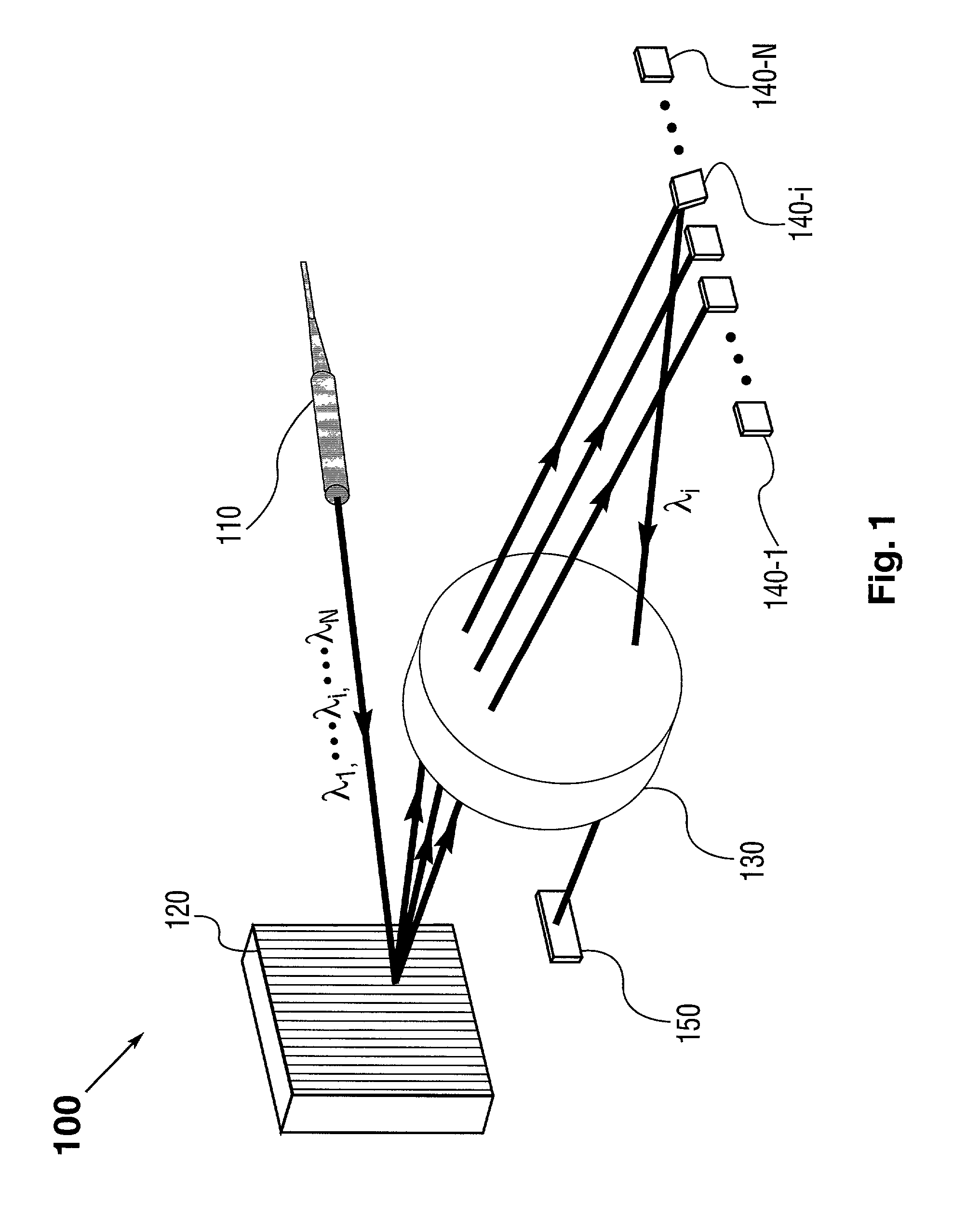
[0020]FIG. 1 shows a perspective view of an optical spectral monitoring apparatus according to the present invention. By way of example to illustrate the general principles of the present invention, optical spectral power monitoring apparatus 100 comprises an input port 110 which may be a fiber collimator; a wavelength-disperser 120 which in one form may be a diffraction grating; a beam focuser 130 which may be a focusing lens; and an array of beam-manipulating elements 140 which in one form may be micromirrors 140-1 through 140-N. The optical spectral monitoring apparatus 100 may further include an optical detector 150, which may be a photodiode in conjunction with an associated detection circuit.

[0021]For purposes of illustration and clarity, only a select few (e.g., three) of the spectral channels, along with the input multi-wavelength optical signal, are graphically illustrated in FIG. 1 and the following figures. It should be noted, however, that there can be any number of the ...

second embodiment

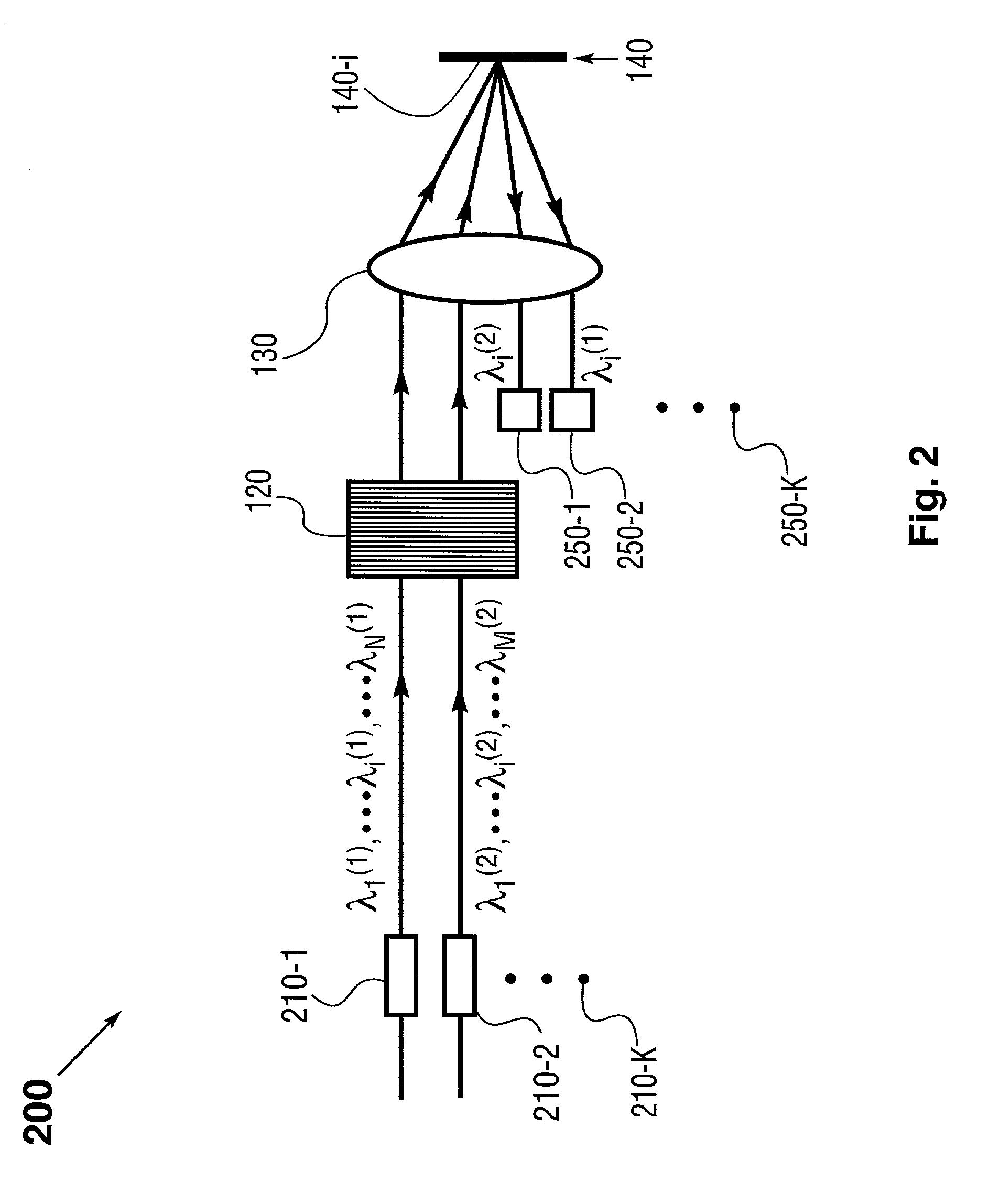
[0026]The embodiment of FIG. 1 may be further extended to provide optical spectral power monitoring of a plurality of input multi-wavelength optical signals. Depicted in FIG. 2 is a schematic side view of an optical spectral power monitoring apparatus of the present invention, pertaining to this situation. (The schematic side and top views in FIG. 2 and the following figures are presented with respect to the perspective view of FIG. 1). By way of example, optical spectral power monitoring apparatus 200 of FIG. 2 may make use of the architecture along with a number of the elements used in FIG. 1, as indicated by those elements labeled with identical numerals. This embodiment implements a plurality of input ports 210-1 through 210-K (K≧2), which may be in the form of fiber collimators. Each input port may transmit an optical signal. As a way of example, a first input port 210-1 may transmit a first multi-wavelength optical signal containing wavelengths λ1(1) through λN(1), and a secon...

third embodiment

[0028]It is known that the diffraction efficiency of a diffraction grating may be polarization-dependent. For instance, the diffraction efficiency of a grating in a standard mounting configuration may be higher for p (or TM) polarization that is perpendicular to the groove lines on the grating than for s (or TE) polarization that is orthogonal to p-polarization, or vice versa. Such polarization-sensitive effects may become appreciable for a grating with a large number of groove lines (per unit length). Hence, in applications where the polarization-sensitive effects are deemed undesirable, a polarization diversity scheme may be implemented in the present invention. FIG. 3 depicts a schematic side view of an optical spectral power monitoring apparatus of the present invention, employing an array of micromirrors as the beam-manipulating elements in a polarization diversity scheme.

[0029]By way of example, optical spectral power monitoring apparatus 300 of FIG. 3 may make use of the gene...


PUM


Abstract

The present invention provides a method and apparatus for optical spectral power monitoring that employ a time-division-multiplexed detection scheme. The optical spectral power monitoring apparatus of the present invention uses a wavelength-dispersing means such as a diffraction grating to separate a multi-wavelength optical signal into multiple spectral channels and an array of beam-manipulating elements positioned to correspond with the spectral channels. The beam-manipulating elements are individually controllable so as to direct the spectral channels into an optical detector in a time-division-multiplexed sequence. The optical spectral power monitoring apparatus may further employ a polarization diversity scheme, thereby becoming polarization insensitive. This enables the apparatus of the present invention to enhance spectral resolution, while providing improved accuracy in optical spectral power detection. Accordingly, a variety of novel optical spectral power monitors can be constructed according to the present invention, that are well suitable for WDM optical networking applications.

Description

FIELD OF THE INVENTION[0001]This invention relates generally to optical spectral monitors and analyzers. More specifically, it relates to novel types of optical spectral monitors employing time-division-multiplexing detection schemes, which are suitable for WDM optical networking applications.BACKGROUND[0002]As optical communication networks employing wavelength division multiplexing (WDM) become increasingly pervasive, a new line of optical performance monitors, including spectral power monitors, is in demand.[0003]Conventional spectral power monitors in the art typically use a wavelength-dispersing means, such as a diffraction grating or a dispersing prism, to separate a multi-wavelength optical signal into a spatial array of spectral channels with distinct center wavelengths. An array of photo-detectors (e.g., photodiodes) is positioned to detect the spectral channels individually, thereby providing an optical power spectrum of the multi-wavelength optical signal. Alternatively, ...

Claims


Application Information

Patent Timeline
Patent Type & Authority Patents(United States)
IPC IPC(8): G02B6/00G01J3/32G02B6/34G02B6/42H04J14/00H04J14/02H04J14/08
CPCG01J3/32G02B6/4249H04J14/02G01J3/021G01J3/0224G02B6/2706G02B6/2793H04J14/08G02B6/29311G02B6/29397G02B6/425G02B6/2931
Inventor POLYNKIN, PAVEL G.GARRETT, MARK H.WILDE, JEFFREY P.
Owner CAPELLA PHOTONICS INC
Why Eureka
Try Eureka