Electronic control unit

a technology of electronic control unit and control unit, which is applied in the direction of electrical control, fault response, instruments, etc., can solve the problems of inability to carry out transmitting and receiving the essentially required data, inability to carry out the operation of the station, and unnecessary downstream communication

Active Publication Date: 2007-02-13
MITSUBISHI ELECTRIC CORP
View PDF10 Cites 21 Cited by
  • Summary
  • Abstract
  • Description
  • Claims
  • Application Information

AI Technical Summary

Benefits of technology

[0020]Accordingly, a first object of the present invention is to provide an electronic control unit that includes first and second control circuit sections electrically divided so as to perform mutual communication of serial signals, the electronic control unit being arranged such that a regular transmission from the first control circuit section acting as a master station to the second control circuit section acting as a sub station, and a regular report from the sub station to the master station can be carried out as required; and furthermore confirmation of presence or absence of any communication error relative to various communication packets, and a retransmission processing can be easily carried out while preventing communication jam-up.
[0021]A second object of this invention is to provide an electronic control unit that is capable of preventing too sensitive error determination with respect to a sporadic and chronic error in which communication error state automatically recovers; and is capable of comprehensively determining number of times of retransmission processing and an error definition timing with respect to a variety of communication errors such as sum check error or timeout error relative to various communication packets.

Problems solved by technology

A problem, however, exists in that a communication jam-up takes place at the time of occurrence of some sort of communication error making it incapable to carry out transmitting and receiving an essentially required data.
Accordingly, reporting from the sub station cannot be carried out without request from the master station, and therefore a regular request comes to be necessary in the case of presence of any regular report data, eventually resulting in a problem that unnecessary downstream communication takes place.
That is, a problem exists in that in case of setting a threshold for determining an error to a large value, any response delay is generated in detection of error occurrence subsequent to a normal communication.
On the other hand, in case of setting a threshold for determining an error to a small value, too-sensitive error detection is carried out even when any slight and sporadic error occurs.
According to the Japanese Patent Publication (unexamined) No. 267948 / 2000, a problem exists in that a computer is reset only with a single timeout.
A further problem exists in that processing of sum check error or retransmission is not described from a comprehensive viewpoint.
According to the Japanese Patent Publication (unexamined) No.235598 / 2002, a problem exists in that although timeout of communication can be detected by monitoring the run-away of microprocessor, communication error in terms of lack or mix in bit such as sum check error is not monitored.

Method used


Image

  • Electronic control unit
  • Electronic control unit
  • Electronic control unit

Examples


embodiment 1

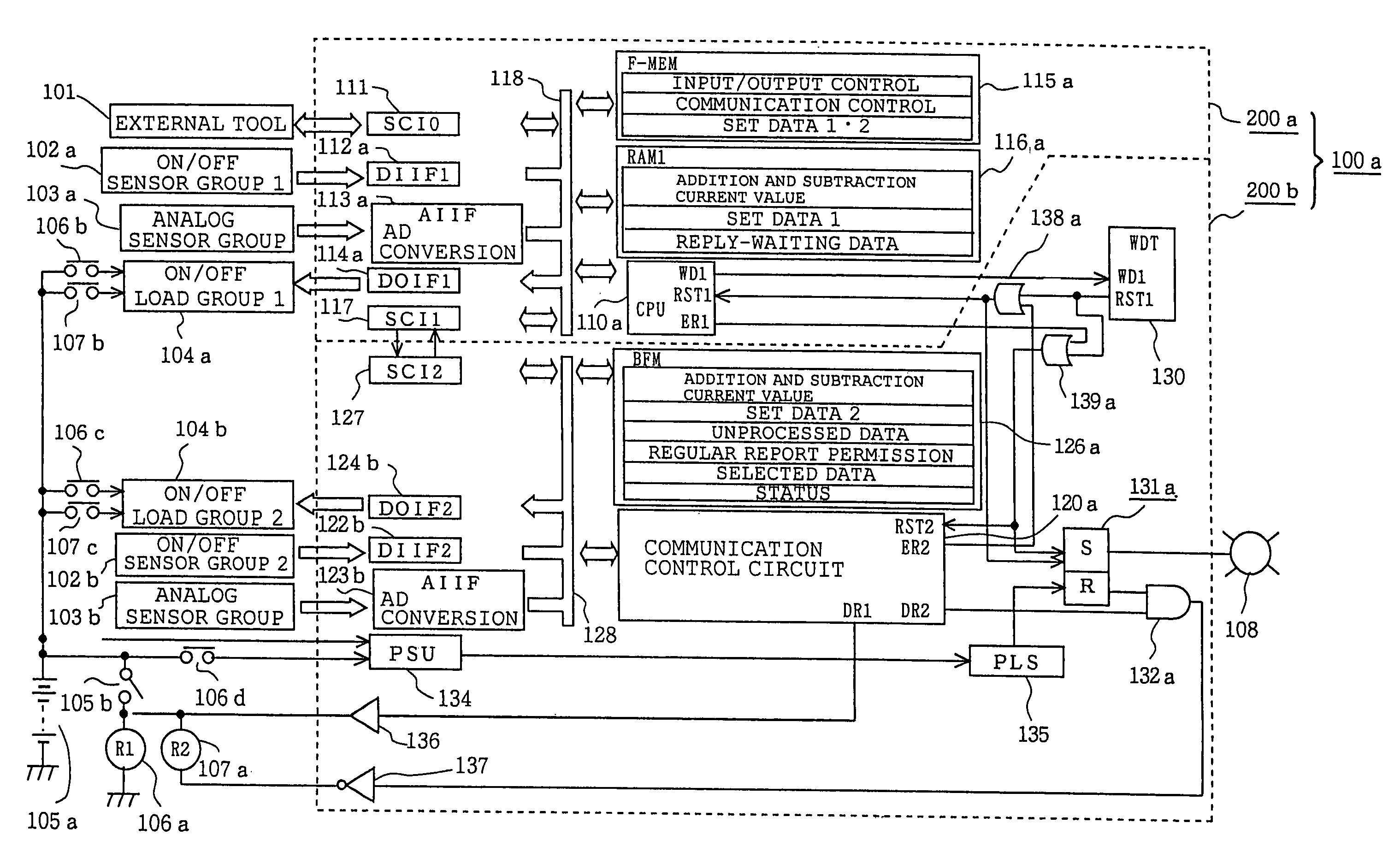
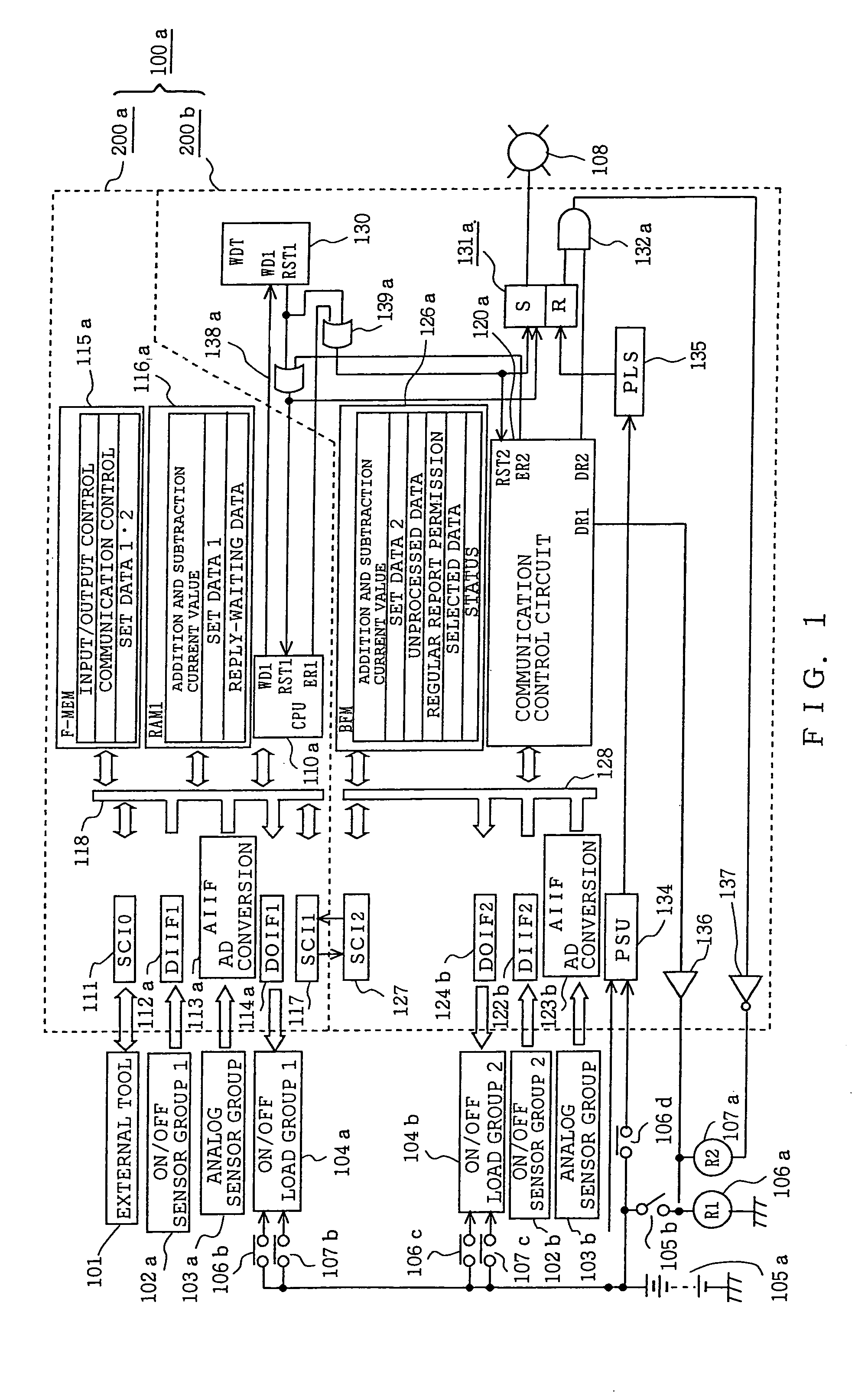
[0096]FIG. 1 is a block diagram showing an entire constitution of an electronic control unit according to a first embodiment.

[0097]With reference to FIG. 1, reference numeral 100a designates an electronic control unit consisting of a first control circuit section 200a and a second control circuit section 200b.

[0098]First, as a component connected to the outside of the above-mentioned electronic control unit 100a, numeral 101 designates an external tool. This external tool 101 is connected via a detachable connector, not shown, to the above-mentioned electronic control unit 100a at the time of dispatching a product or maintenance inspection thereof, and functions to transfer and write a control program or a control constant to the later-described non-volatile program memory 115a.

[0099]Numeral 102a designates a first input sensor group (for example, an engine speed sensor, a crank angle sensor, and a speed sensor) that performs an ON / OFF operation. This first input sensor group 102a...

embodiment 2

[0282]FIG. 11 is a block diagram showing an entire constitution of an electronic control unit according to a second preferred embodiment.

[0283]Hereinafter, constitution and operation of the electronic control unit according to the second embodiment are described, focusing on points different from the electronic control unit according to the foregoing first embodiment shown in FIG. 1.

[0284]With reference to FIG. 11, numeral 100b designates an electronic control unit that consists of a first control circuit section 210a and a second control circuit section 211b. Numeral 110b designates a main CPU (microprocessor). Numeral 115b designates a non-volatile program memory such as flash memory cooperating with the foregoing main CPU 110b. Written in the above-mentioned program memory 115b are a program acting as input / output control means, or a program acting as communication control means, as well as a set data to be transferred and written in the first and second set data memory 237a and ...


PUM


Abstract

An electronic control unit includes a serial communication circuit capable of easily confirming presence or absence of communication error while regular transmission / regular report between master station and sub station are performed timely. First and second control circuit sections 200a (master station) and 200b (substation) communicate mutually via series-parallel converters 117, 127. The master station includes regular transmission device 201 and irregular transmission device 211. The substation includes regular report device 221, confirmation reply device 205 and report reply device 215 relative to transmission data from the master station, and unprocessed data table 204. The confirmation reply device 205 and report reply device 215 confirm whether or not downstream communication from the master station to sub station is normal. When any error is present in regular report data through upstream communication, the error is confirmed on the fact the irregular transmission device 211 makes retransmission readout request.

Description

[0001]This application is related to application Ser. No. 10 / 788,370, filed on Mar. 1, 2004 commonly assigned with the present invention.BACKGROUND OF THE INVENTION[0002]1. Field of the Invention[0003]The present invention relates to an on-vehicle electronic control unit having a microprocessor built-in for use in, for example, a fuel supply control of an automobile engine and, more particularly, to an improvement of an electronic control unit that includes a plurality of control circuit sections electrically divided so as to carry out a mutual communication of serial signals.[0004]2. Description of the Related Art[0005]Electronic control unit in which information exchange by a method of serial communication is carried out among a plurality of microprocessors sharing functions, and communication error is detected to carry out error processing, has been practically and widely used in various fields.[0006]For example, according to the Japanese Patent Publication (unexamined) No. 10883...

Claims


Application Information

Patent Timeline
Patent Type & Authority Patents(United States)
IPC IPC(8): G06F11/00F02D45/00G06F11/07G06F11/30G06F13/00H04L12/40
CPCG06F11/0736G06F11/0739H04L1/1867H04L1/1829G06F11/0757G06F11/0793
Inventor HASHIMOTO, KOHJINAKAMOTO, KATSUYAIWAGAMI, YUKIISHII, AKIHIRO
Owner MITSUBISHI ELECTRIC CORP
Why Eureka
Try Eureka