
Sheet moulding compound (SMC) with ventilating structure for entrapped gases

Inactive Publication Date: 2007-02-20
GURIT (UK) LTD
View PDF16 Cites 13 Cited by
  • Summary
  • Abstract
  • Description
  • Claims
  • Application Information

AI Technical Summary

Benefits of technology

[0021]In an embodiment of the invention, the ventilating structure may be formed by said reinforcement material. We have discovered that trapped gases inside the laminate are released from the moulding material by providing a conduit via which these gases can conveniently escape during curing of the moulding material. The conduit is formed by the reinforcement material which is dry or partially impregnated with the resin material. This open structure allows gases such as inter-laminar and intra-laminar gases, to escape from the laminate through the reinforcement layer which acts as an air bleeder structure. In this way the reinforcement layer is fully wetted out by the resin which results in a smooth surface finish of the processed moulding material.
[0075]In conventional prepregs that are processed under vacuum consolidation, it is important that dry areas of reinforcement fibres are avoided since they generally do not completely wet out during the processing of the prepreg which may lead to areas of weakness in the finished product. However, where the moulding materials of the present invention are used, the fibrous layer is specifically not wet out during production of the prepreg but will be completely wet out during the processing.

Problems solved by technology

Although the products thus formed were satisfactory, it was difficult to guarantee the quality of the product due to the difficulty in controlling the ratio of the resin to the reinforcement fibres.
One of the main problems associated with this moulded material is that the surface properties of this material are not ideal.
These pin-holes and cracks can develop into blisters during the life of the material.
This makes the production of mouldings from this material generally labourious, inefficient and expensive.
However, after the moulding material has cured, the reinforcement fibres, which are present in the surface layer, can be observed through the surface layer due to shrinkage of the resin.
Further, reinforcement fibres in the surfacing layer which are not sufficiently embedded in resin, result in pin-holes on the surface.
This prevents the material from being readily applied or coated without carrying out surface treatment operations such as fairing, filling or coating.
A further disadvantage of this material, which we noted during the application testing of the material, is that, due to the high resin loading of the material, the prepreg material is difficult to apply in complex moulds since it is quite stiff and relatively inflexible (low drape).
Another factor which we encountered with this alternative material is that this material has little porosity through its thickness, so that substantial volumes of laminar gases such as air are trapped inside the laminate and on the surface of the mould during processing of the material, which results in voids in the cured laminate.
Such voids result in the laminate having reduced mechanical properties which can lead to premature failure of the composite material.

Method used


Image

  • Sheet moulding compound (SMC) with ventilating structure for entrapped gases
  • Sheet moulding compound (SMC) with ventilating structure for entrapped gases
  • Sheet moulding compound (SMC) with ventilating structure for entrapped gases

Examples


Embodiment Construction

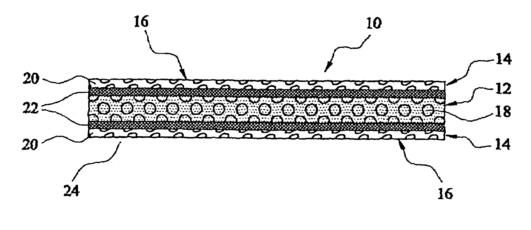
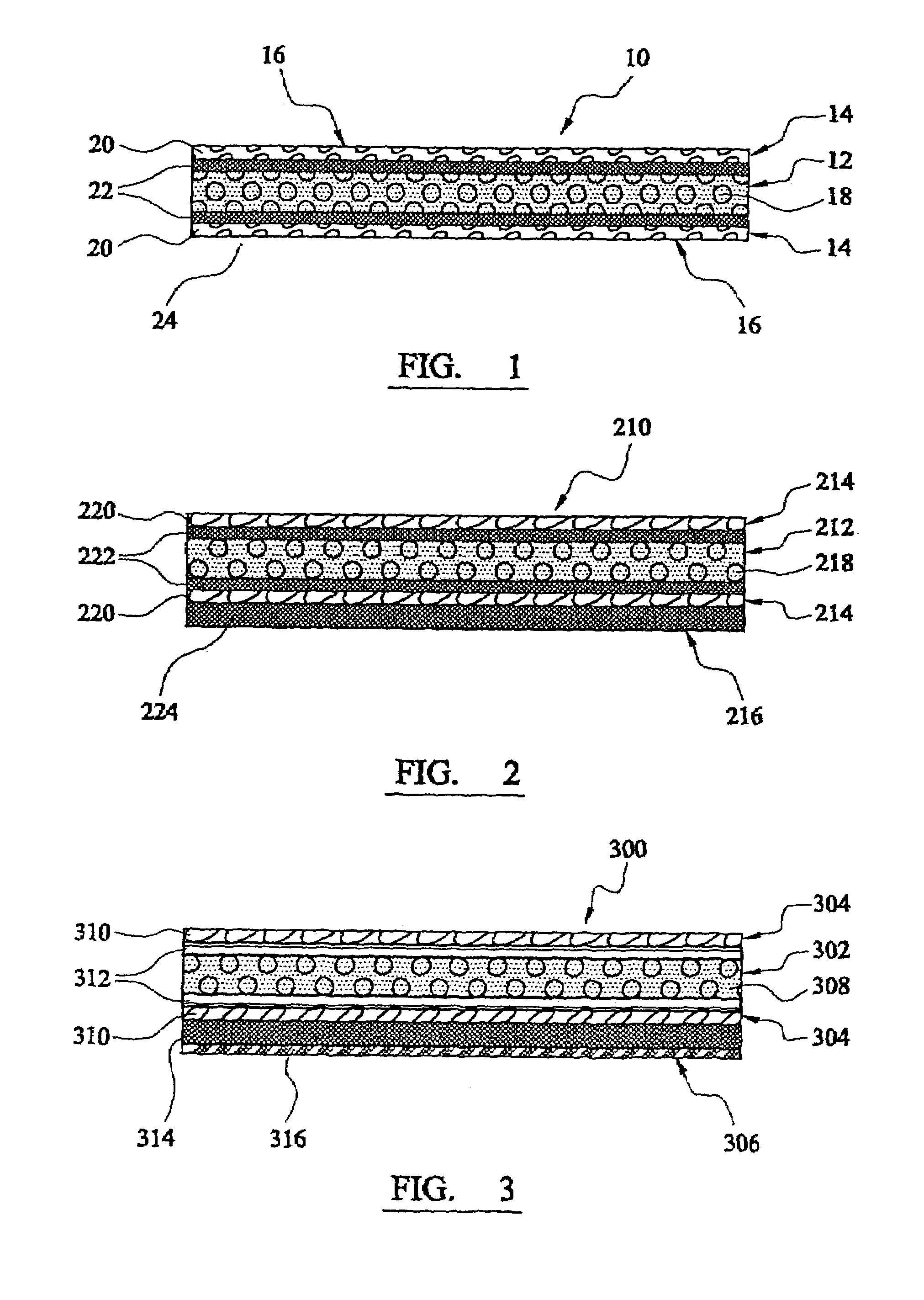
[0089]The moulding material 10 comprises a core layer 12, reinforcement layers 14 and external surfaces 16. The core layer 12 comprises a core resin and a hollow filler 18. The reinforcement layers 14 are provided on each side of the core layer 12. The reinforcement layers 14 comprise a fibrous reinforcement material 20 and a reinforcement resin 22 which is provided between the core layer 12 and the reinforcement material 20. In an alternative embodiment (not shown) the reinforcement material 20 can be partially preimpregnated by the reinforcement resin 22. The reinforcement layer 14 further comprises a conduit structure which allows gases to pass out of the moulding material 10 via the reinforcement layer 14 during processing. The conduit or ventilating structure is formed by the reinforcement material 20.

[0090]When fabricating or manufacturing an article of the moulding material 10, the moulding material 10 is applied to a mould such that the external surface 16 of one of the rein...


PUM

PropertyMeasurementUnit
Flow rateaaaaaaaaaa
Structureaaaaaaaaaa
Viscosityaaaaaaaaaa

Abstract

Moulding material comprising a core layer, a reinforcement layer provided on each surface of said core layer, and a layer of a surfacing material provided on a reinforcement layer. The core layer comprises a core resin material and a filler material. The reinforcement layer comprises a fibrous reinforcement material and a reinforcement resin material. The reinforcement layer further comprises a conduit to allow gases to pass out of the moulding material via the reinforcement layer during processing of the moulding material whereby the conduit structure is formed by said reinforcement material.

Description

CROSS REFERENCE TO RELATED APPLICATION[0001]This application is a continuation of co-pending International Application No. PCT / GBO1 / 04414, filed Oct. 3, 2001 and which designated the U.S.BACKGROUND OF THE INVENTION[0002]The present invention relates to a moulding material, particularly but not exclusively to a moulding material suitable for manufacturing lightweight articles which have a smooth surface finish and good mechanical properties.[0003]Historically, moulded articles or mouldings were formed from resin either alone or reinforced with a fibrous reinforcement material. Although the products thus formed were satisfactory, it was difficult to guarantee the quality of the product due to the difficulty in controlling the ratio of the resin to the reinforcement fibres. The process was therefore refined such that the supplier of the resin provided the producer of the moulded article with preformed pre-impregnated reinforcement material known as a ‘prepreg’. This moulding material a...

Claims


Application Information

Patent Timeline
IPC IPC(8): B32B5/14B29C70/02B32B3/24B32B37/04B32B37/10B32B5/16D04H1/00B29C39/10C08J5/24B29C70/46B29C70/54B29K105/06B29K105/16B32B27/12B32B27/20
CPCB29C70/46B29C70/547B32B27/12B32B27/20Y10T428/24331Y10T428/24124Y10T428/24074Y10T428/249946Y10T428/249924Y10T428/249945Y10T442/2926Y10T442/2738Y10T442/3854Y10T442/674
Inventor JONES, DANIEL THOMASNESS, DEREK SIMON RICHARD
Owner GURIT (UK) LTD
Learn More