
Battery charging method

a battery and charging method technology, applied in the field of battery rapid charging, can solve the problem of not being able to rapidly charge a and achieve the effect of reducing the duty factor of the charging current, reducing the temperature rise of the battery, and rapid charging of the battery in a short tim

Inactive Publication Date: 2007-02-20
SANYO ELECTRIC CO LTD
View PDF4 Cites 6 Cited by
  • Summary
  • Abstract
  • Description
  • Claims
  • Application Information

AI Technical Summary

Benefits of technology

The present invention provides a battery charging method that can rapidly charge a battery without degrading its performance. The method charges while maintaining battery temperature at a set holding temperature, which can be 50-65°C, using a temperature maintaining charging step. The method can also have a temperature increasing charging step, prior to the temperature maintaining charging step, where the battery is charged with high current to raise its temperature to the holding temperature. The method can control average charging current to maintain battery temperature at the holding temperature. The method can also detect battery temperature at the beginning of charging and start the temperature increasing charging step if battery temperature is within a specified range. The charging method provides continuous current flow to the battery during the temperature maintaining charging step and can suspend charging if the rate of battery temperature increase exceeds a specified rate.

Problems solved by technology

As a consequence, although the charging method of this same disclosure can prevent battery temperature from rising abnormally high at full charge, it cannot rapidly charge a battery in a short time.
For example, it is possible to rapidly charge a battery with high current at the holding temperature, which is near the maximum value but still below the temperature where performance degradation and deleterious effects occur to the battery being charged.

Method used


Image

  • Battery charging method
  • Battery charging method
  • Battery charging method

Examples


Embodiment Construction

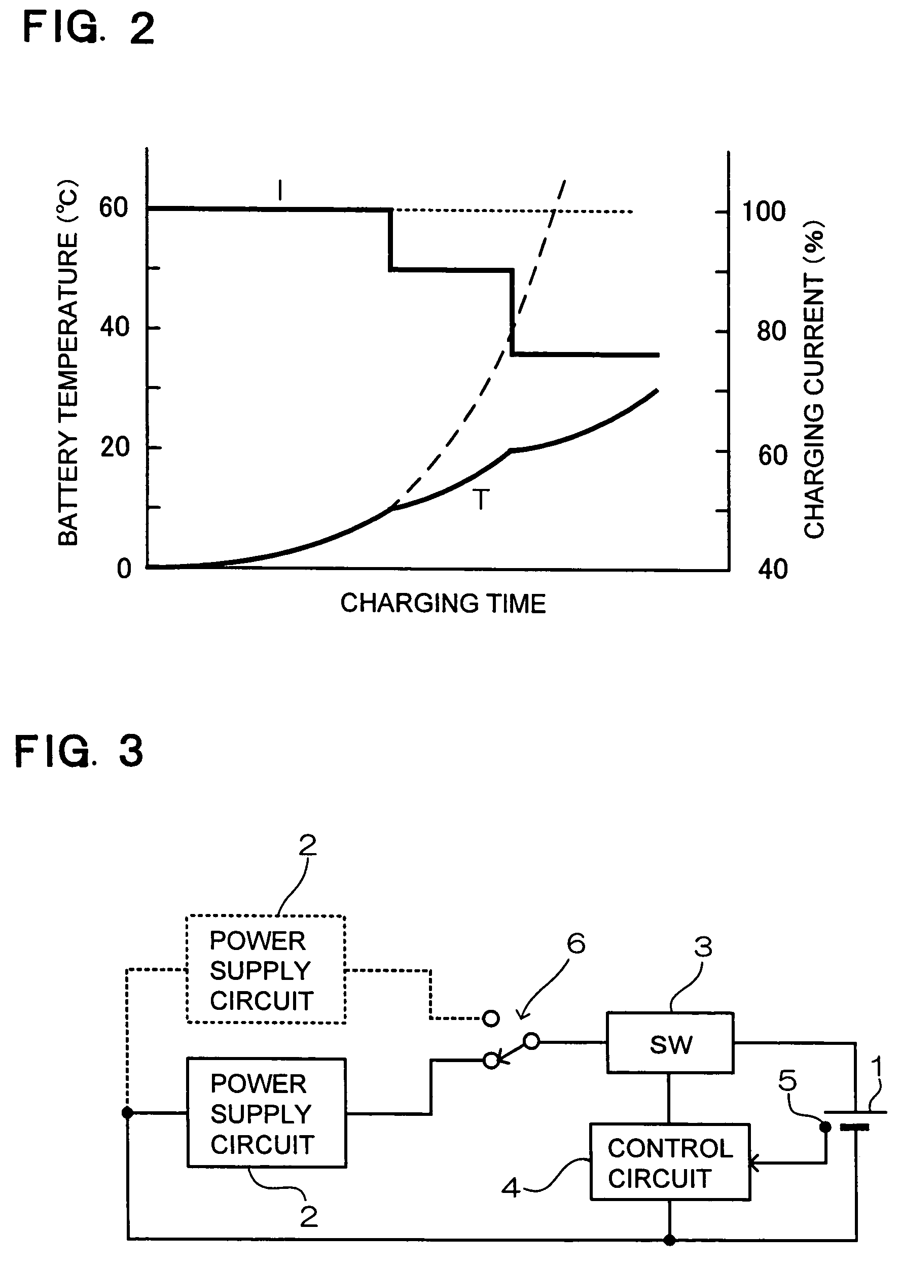
[0021]The charging circuit shown in FIG. 3 is provided with a power supply circuit 2 to supply charging current to charge the battery 1, a switching device 3 connected between the power supply circuit 2 and the battery 1 to regulate average charging current to the battery 1, a control circuit 4 to control charging current by switching the switching device 3 on and off, and a temperature sensor 5 to detect battery temperature and input a temperature signal to the control circuit 4.

[0022]When a standard size battery (TAN 1–4), such as size D, C, AA, AAA, is used, the temperature sensor 5 is disposed in intimate contact with the battery 1 when it is set in a battery charger adapter (not illustrated). When the battery 1 is a battery pack, the temperature sensor 5 is disposed inside the battery pack in intimate contact with the battery itself.

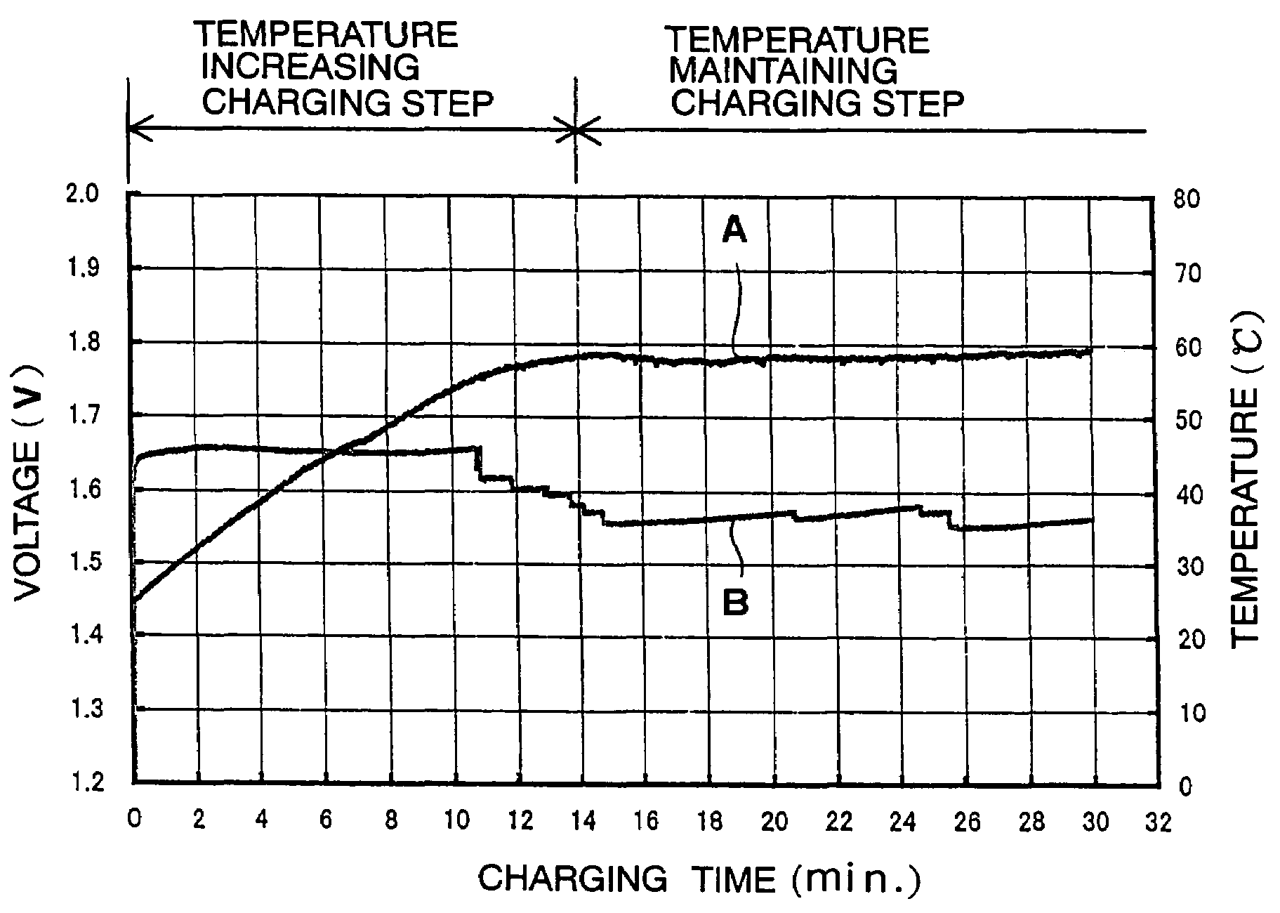
[0023]The graph of FIG. 4 shows battery temperature rise and battery voltage variation characteristics when a battery 1 is charged with the chargin...


PUM

PropertyMeasurementUnit
temperatureaaaaaaaaaa

Abstract

The battery charging detects battery temperature and includes a temperature maintaining charging operation wherein average charging current is controlled to drive battery temperature to a holding temperature, and charging is performed while maintaining battery temperature at that holding temperature. In addition, a temperature increasing charging operation occurs prior to the temperature maintaining charging operation. The battery is charged with a current which raises battery temperature until the holding temperature is reached. When battery temperature rises to the holding temperature in the temperature increasing charging operation, charging can transition to the temperature maintaining charging operation.

Description

BACKGROUND OF THE INVENTION[0001]This invention relates to a method for rapidly charging a battery in as short a time as possible.[0002]There are essentially two types of related art battery charging methods which rapidly charge a battery. The first type of charging method charges a battery with a constant current until full charge is reached. This charging method is adopted for nickel hydrogen batteries and nickel cadmium batteries. This charging method detects peak battery voltage or a ΔV voltage drop from the peak battery voltage to determine full charge and terminates charging. The second type of charging method performs constant voltage charging after constant current charging, and is adopted for lithium ion batteries. This charging method detects voltage rise until a charging termination voltage is reached, then full charge is assumed and charging is terminated.[0003]These types of charging methods continuously charge primarily while detecting battery voltage. However, battery...

Claims


Application Information

Patent Timeline
Patent Type & Authority Patents(United States)
IPC IPC(8): H02J7/04H02J7/06H02J7/16H02J7/24H01M10/44H01M10/60H01M10/615H01M10/633H01M10/643H01M10/651H02J7/00H02J7/10
CPCH02J7/0091H02J7/0073H02J7/0071H02J7/007194
Inventor IZUMI, YOSHIKAZUKURODA, YASUSHIFURUKAWA, AKIOYAMASHITA, TAKAHIRO
Owner SANYO ELECTRIC CO LTD
Learn More