Method and apparatus to diagnose intake airflow

a technology of intake air and diagnostic equipment, applied in the direction of electrical control, testing/monitoring control system, instruments, etc., can solve the problem of complex calculations that otherwise would be very difficult to model with simple mathematical equations, and achieve the effect of minimizing errors

Inactive Publication Date: 2007-02-20
GM GLOBAL TECH OPERATIONS LLC
View PDF8 Cites 14 Cited by
  • Summary
  • Abstract
  • Description
  • Claims
  • Application Information

AI Technical Summary

Benefits of technology

[0004]The present invention is a method and apparatus for diagnosing sensors in an internal combustion engine (ICE) using neural networks. A Neural Network (NN) is a mathematical tool that is used to perform complex calculations. It is a tool used to produce an equation or transfer function that relates known inputs to known outputs. A NN is trained on data exemplars that associate input values with desired output values. The training process involves adjusting internal NN weights in a manner that will minimize th...

Problems solved by technology

Using either method, once the NN is fully trained and embedded in a control system, it will have the ability ...

Method used


Image

  • Method and apparatus to diagnose intake airflow
  • Method and apparatus to diagnose intake airflow
  • Method and apparatus to diagnose intake airflow

Examples


Embodiment Construction

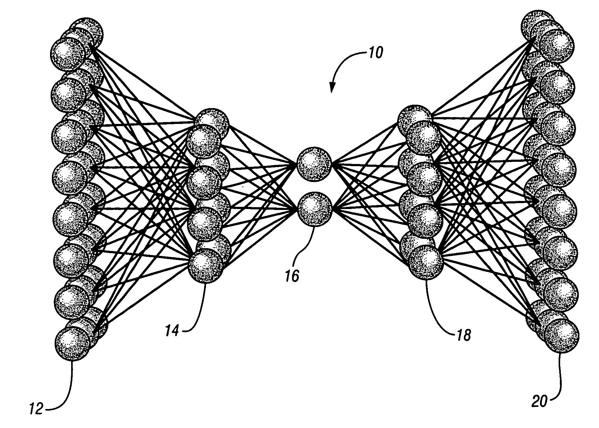
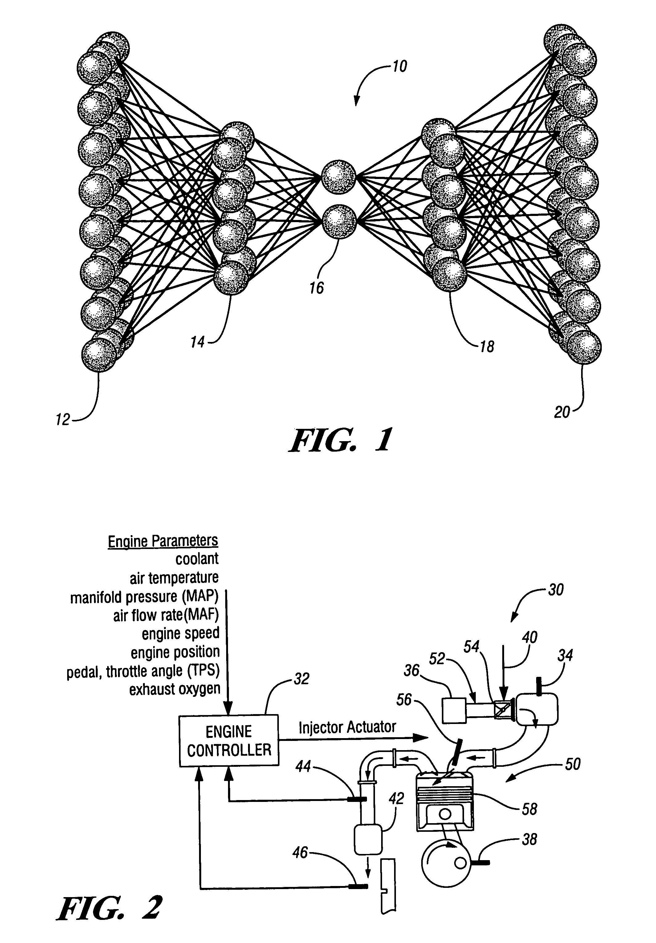
[0016]FIG. 1 is a diagrammatic drawing of an Auto Associative Neural Network (AANN) 10 including an input layer 12; three hidden layers comprising a mapping layer 14, a bottle-neck layer 16, a de-mapping layer; and an output layer 20. The overall transfer function of the AANN 10 of the present invention is equal to 1, as the outputs are trained to be equal to the values on the corresponding inputs. The design of the AANN 10 uses compression of data in the bottleneck layer 16 to achieve an overall transfer function that is not trivially equal to 1. For this type of AANN to work properly, the input data has the property of analytical redundancy where the inputs to the AANN 10 are physically related somehow. The analytically redundant information will be used to generate correct output values when the inputs are only partially correct or in a fault condition. For example, when a sensor is faulty on one input, there is enough information coming from the other inputs to generate a correc...


PUM


Abstract

An engine control system including an engine controller, a plurality of sensors coupled to the engine controller, and a neural network operating in the engine controller, and where upon failure of at least one of the plurality sensors, the neural network generates a representative value of the failed sensor.

Description

TECHNICAL FIELD[0001]The present invention relates to internal combustion engine controls. More specifically, the present invention relates to a method and apparatus for diagnosing sensors operating with an internal combustion engine.BACKGROUND OF THE INVENTION[0002]Today's automotive engine control system consists of engine sensors and actuators wired directly to an electronic control unit (ECU) or controller that contains embedded software. The complexity of the software continues to increase as the number of sensors and actuators used on the vehicle increases. Under current governmental regulations, each emission related sensor must be diagnosed such that faulty sensors are replaced as soon as possible to minimize pollution and poor vehicle performance. For this reason, each sensor is monitored by a diagnostic algorithm that is responsible for detecting sensor values that are irrational or out of range. There are countless ways that a diagnostic may differentiate a good sensor fr...

Claims


Application Information

Patent Timeline
IPC IPC(8): B60T7/12G06F19/00F02D45/00F02D41/22G05B9/02G05B23/02G06G7/70
CPCF02D41/222G05B9/02G05B23/024F02D41/1405Y02T10/40F02D2200/0408
Inventor KROPINSKI, MICHAEL A.MIOTKE, MARK D.
Owner GM GLOBAL TECH OPERATIONS LLC
Why Eureka
Try Eureka