
Sheet material cutting method for cutting thermal imaging material

Inactive Publication Date: 2007-02-27
FUJIFILM CORP
View PDF30 Cites 15 Cited by
  • Summary
  • Abstract
  • Description
  • Claims
  • Application Information

AI Technical Summary

Benefits of technology

[0026]A general object of the invention is to provide a sheet material deformation correcting method and apparatus which can correct the deformation such as the curl of a sheet material reliably for a short time and can reduce the size of the entire facilities.
[0027]On the other hand, a main object of the invention is to provide a sheet material deformation correcting method and apparatus which can subject a recording medium having various recording layers of different heat resistances to a desired decurl treatment without affecting the quality of the recording medium adversely.
[0028]Another main object of the invention is to provide a sheet material deformation correcting method and apparatus which can decurl the sheet material reliably and easily and can keep the sheet material in a high quality.
[0029]Still another main object of the invention is to provide a sheet material deformation correcting method and apparatus which can decurl the sheet material reliably and easily without being influenced by the change in the treating rate.
[0030]A further main object of the invention is to provide a sheet material deformation correcting method and apparatus which can flatten a polymer sheet material reliably without being influenced by the change in the kind of the polymer sheet material or the running situation.
[0031]A further main object of the invention is to provide a sheet material cutting method and apparatus which can cut a thermal imaging sheet material satisfactorily without depending upon the shapes of blades or the adjusting conditions of upper and lower blades.

Problems solved by technology

This raises a problem that the transferability and stackability of the image recording carrier sheets are seriously deteriorated.
When the image recording carrier sheet is treated by various machines such as a developer or printer, moreover, its transfer or image formation is so troubled that it cannot be subjected to a desired treatment.
As the case may be, the existence of the curl after the image formation may cause a problem in the quality.
For the practical decurl operation, it takes a considerably long heating time.
As a result, the decurl treatment is not efficient to cause problems that the stock loss of the film occurs, and that the facilities become large-sized.
Still the worse, the elongated heating time may deteriorate the image characteristics of the recording layer.
If the heating treatment for the time period as long as 2 to 20 secs. is performed at such high temperature, the image recording layer is affected to raise a problem that the image characteristics are seriously deteriorated.
Depending upon the kind, therefore, there is pointed out a problem that the quality is troubled by the thermal fogging, the color tone fluctuation, the crack, or the like.
According to the change in the processing rate, moreover, the heating conditions may change to make the calorie short or excessive.
Thus, there are various problems that the desired decurl effect cannot be obtained, and that the quality is degraded.
In the aforementioned Prior Art 3, however, it is extremely difficult to control the temperature or flow of the hot wind highly responsively and precisely according to the curl of the roll paper, as sequentially changed with the remainder or the like of the roll paper.
Thus, there has been pointed out a problem that the desired decurl effect cannot be reliably obtained for the roll paper.
Depending upon the kind, moreover, the rolled sheet material to be decurled may be troubled in its quality by the overheat.
There is pointed out a problem that the aforementioned Prior Art 4 cannot be applied to the apparatus of this kind.
This is because the change in the working rate will change the curl-removing (or decurl) effect so that the desired decurl treatment cannot be efficiently effected.
This cut end mark phenomenon affects the aforementioned step of applying the recording layer thereby to raise a problem that a coating unevenness of the recording layer is caused to deteriorate the quality.
At the working step, therefore, the several turns in the vicinity of the roll core are generally dumped to raise a disadvantage that the production yield drops to an uneconomical level.
As a result, the film may be over-heated and elongated.
Since the image forming layer (such as a photosensitive layer or a heat-sensitive layer) of the thermal imaging material is thick and fragile, however, there will easily arise degradations such as the film separation, the crack and the separation from the film base by the cutting action.
As a result, there is a problem that the image forming layer is degraded.
However, the adjustment of the-shapes or the snipping angle of the upper blade and the lower blade of the prior art is defective in that it cannot solve the problems of the film separation, the crack and the peel from the film base by the cutting operations.
On the other hand, the adjustments of the shapes and the snipping angle of the upper blade and the lower blade are so delicate that they are difficult to maintain.
At the time of cutting the thermal imaging material, therefore, there will easily arise a trouble that the surface film peels in a beard shape, comes out as chips or cracks in the image forming layer.
As shown in FIG. 65, on the other hand, there is another problem that when the thermal imaging material 1 is to be slit, there is a problem that a banking 7 occurs, on the side cut by the upper blade, on the image forming layer whereas a crack 8 occurs, on the side cut by the lower blade, in the image forming layer 3.

Method used


Image

  • Sheet material cutting method for cutting thermal imaging material
  • Sheet material cutting method for cutting thermal imaging material
  • Sheet material cutting method for cutting thermal imaging material

Examples


first embodiment

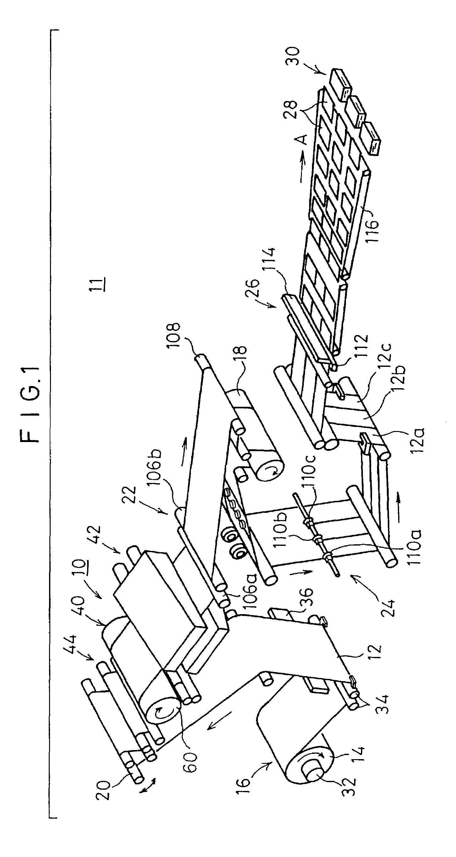
[0098]FIG. 1 is a perspective explanatory view showing a schematic construction of a sheet film processing system 11, into which a decurl apparatus (or deformation correcting apparatus) 10 according to the invention is incorporated.

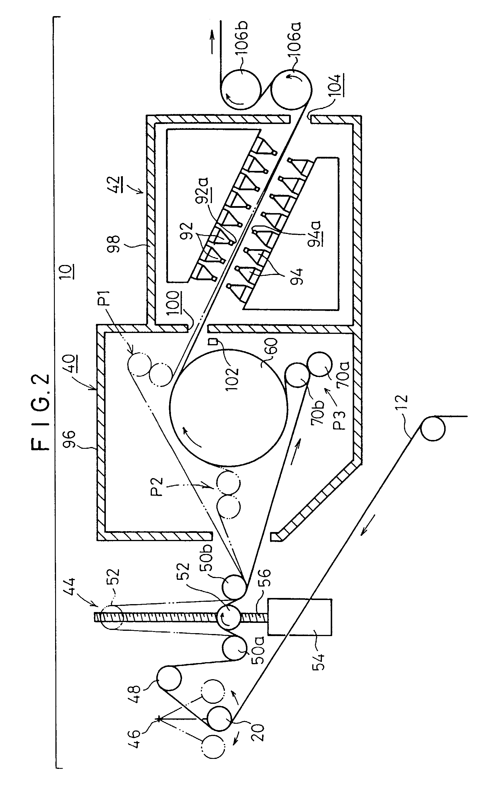
[0099]This sheet material processing system 11 is constructed to include: a web unwinder 16, in which a roll film 14 having an image recording carrier web (or sheet material) 12 rolled thereon is mounted, for letting off the image recording carrier web 12 from the roll film 14; a main feeding suction drum 18 for feeding the image recording carrier web 12 at a predetermined velocity from the web let-off unit 16; a dancer roller 20 for adjusting the tension of the image recording carrier web 12; the decurl apparatus 10, as arranged downstream of the dancer roller 20, and a cooler unit 22 for cooling the image recording carrier web 12, as let off the decurl apparatus 10; a slitter unit 24 arranged downstream of the suction drum 18, for slitting the image rec...

third embodiment

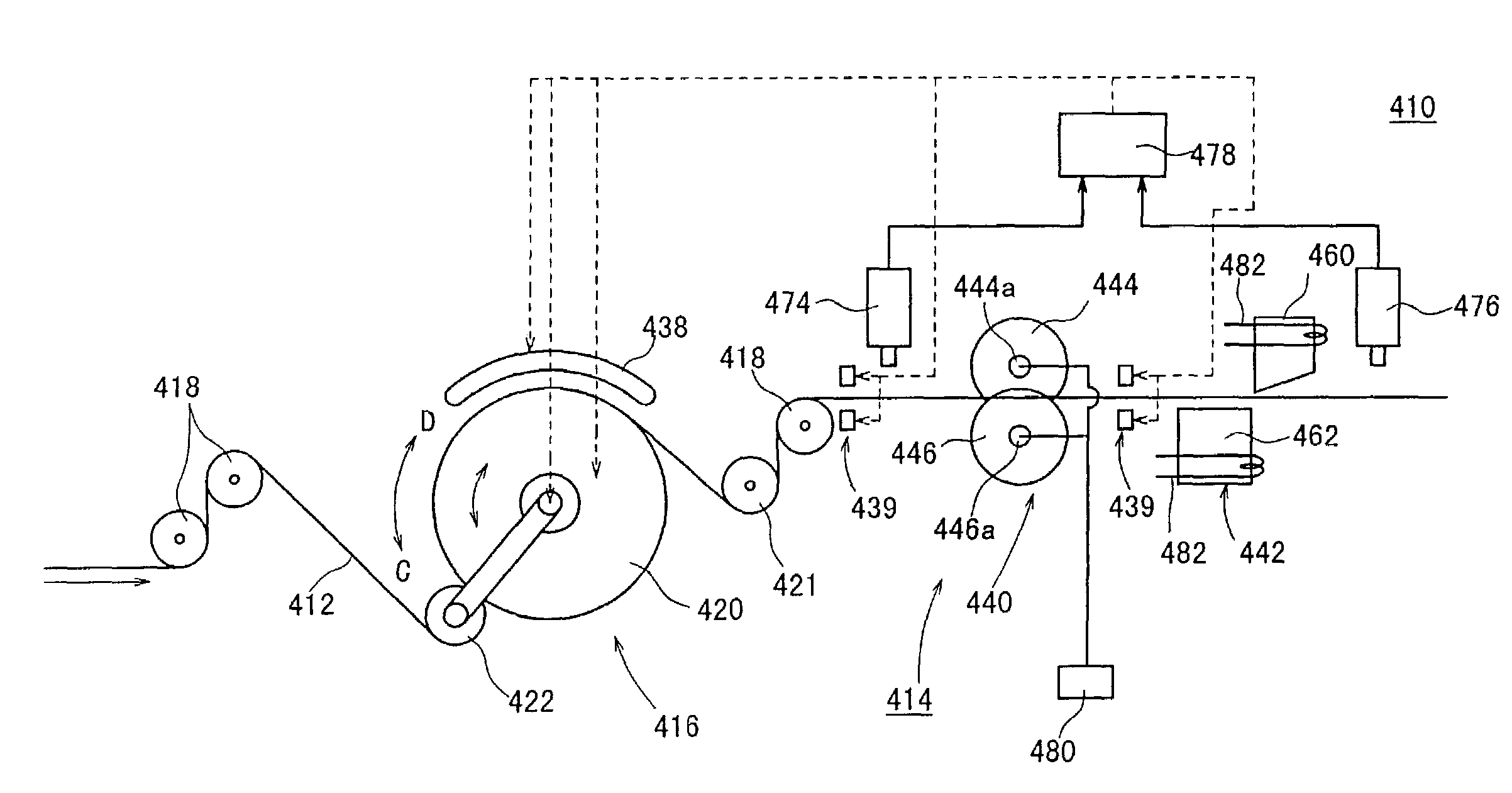
[0143]FIG. 13 is a schematic diagram for explaining heating means 160 composing a decurl apparatus according to the invention.

[0144]The heating means 160 is equipped with: first and second heating rollers 162 and 164 for lapping the image recording carrier web 12 thereon in the S-shape at a predetermined spacing from each other; and drive means 168 for turning the first and second heating rollers 162 and 164 integrally on a middle point 166 of the straight line joining the individual centers of the first and second heating rollers 162 and 164.

second embodiment

[0145]These first and second heating rollers 162 and 164 are heated like the heating roller 60 by the induction heating method to a temperature exceeding the glass transition temperature (Tg) of the support of the image recording carrier web 12. On the other hand, the drive means 168 is provided with the (not-shown) worm gear, as in the holding roller displacing means 144 composing the decurl apparatus 140 according to the

[0146]In the heating means 160 thus constructed, when the first and second heating rollers 162 and 164 are arranged at a position P1a, as indicated by solid lines, the image recording carrier web 12 is lapped within a predetermined range (of a lapping angle of 200 degrees, for example) around the first and second heating rollers 162 and 164 so that it is subjected to the heating treatment from its support side.

[0147]When the image recording carrier web 12 is transferred at a low velocity, the first and second heating rollers 162 and 164 are turned in the direction ...


PUM

PropertyMeasurementUnit
Thicknessaaaaaaaaaa
Thicknessaaaaaaaaaa
Glass transition temperatureaaaaaaaaaa

Abstract

A decurl apparatus includes a heating device to heat an image recording carrier web at a constant temperature, which exceeds the glass transition temperature of a support for a constant time period; and a cooling device for subsequent cooling of the image recording carrier web to a temperature equal to or lower than the glass transition temperature, while the image recording carrier web maintains a predetermined shape. The heating device includes an induction-heated heating roller and holding rollers arranged at arbitrary angular positions with respect to the outer circumference of the heating roller. As a result, the image recording carrier web is reliably decurled by a simple construction without being influenced by a transfer velocity or the like.

Description

[0001]This is a divisional of application Ser. No. 09 / 676,667 filed Oct. 2, 2000 now U.S. Pat. No. 6,613,253; the disclosure of which is incorporated herein by reference.BACKGROUND OF THE INVENTION[0002]1. Field of the Invention[0003]The present invention relates to sheet material deformation correcting method, cutting method, deformation correcting apparatus and cutting apparatus for correcting a deformation such as a curl of a rolled sheet material and for cutting the rolled sheet material.[0004]2. Description of the Related Art[0005]Generally, the various image recording carriers (or sheet materials) such as photographic photosensitive material, heat-sensitive sheets of paper or pressure-sensitive sheets of paper having polymer supports (or polymer sheet materials) are formed, for example, by applying a recording layer (or photographic emulsion layer) to the support. This support is made of polyethylene terephthalate (PET), polyethylene naphthalate (PEN) or polyethylene laminate ...

Claims


Application Information

Patent Timeline
IPC IPC(8): B26D7/10B29C53/84B29C53/18B26D1/00B26D9/00B32B43/00
CPCB26D1/0006B26D7/10B26D9/00B29C53/18B32B43/003B65H23/34B26D1/085B26D1/225B26D7/32B65H2301/4148B26D2001/0046B26D2001/0053B26D2001/0066B26D2001/004Y10T83/283Y10T83/041Y10T83/293
Inventor NEGISHI, YOSHIHISAOYAMADA, TAKAYOSHI
Owner FUJIFILM CORP
Features
  • Generate Ideas
  • Intellectual Property
  • Life Sciences
  • Materials
  • Tech Scout
  • Unparalleled Data Quality
  • Higher Quality Content
  • 60% Fewer Hallucinations
Learn More