Electric power steering apparatus
a technology of electric power steering and steering shaft, which is applied in mechanical devices, transportation and packaging, and can solve problems such as difficulty in reducing the length of the motor, deterioration of the ease of assembly operation, and generation of vibration or changes in characteristics. , to achieve the effect of reducing the length
- Summary
- Abstract
- Description
- Claims
- Application Information
AI Technical Summary
Benefits of technology
Problems solved by technology
Method used
Image


Examples
first embodiment
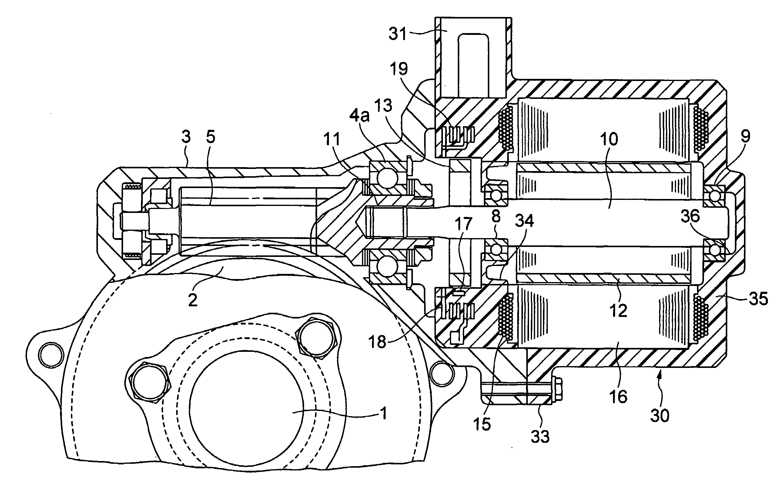
[0090]FIG. 1 is a longitudinal cross sectional view showing an electric power steering apparatus according to the invention.
[0091]As shown in FIG. 1, an output shaft 1 is linked with an input shaft (not shown), which is coupled with a steering wheel (not shown), by means of a torsion bar (not shown). A worm wheel 2 of a worm gear reduction mechanism is fixedly mounted on the output shaft 1.
[0092]A worm 5 rotatably supported in a gear housing 3 by bearings 4a and 4b is in engagement with the worm wheel 2.
[0093]The gear housing 3 is coupled with a motor cover 7 for a brushless motor. The rotor 10 of the brushless motor and the worm 5 are connected by means of a spline fitting portion 11 so that they are movable in the axial direction but non-rotatable relative to each other.
[0094]In the radially outer periphery of the rotor 10, there is provided a cylindrical permanent magnet 12 for rotational driving in such a way as to be opposed to a laminated core 16 that will be described later. ...
second embodiment
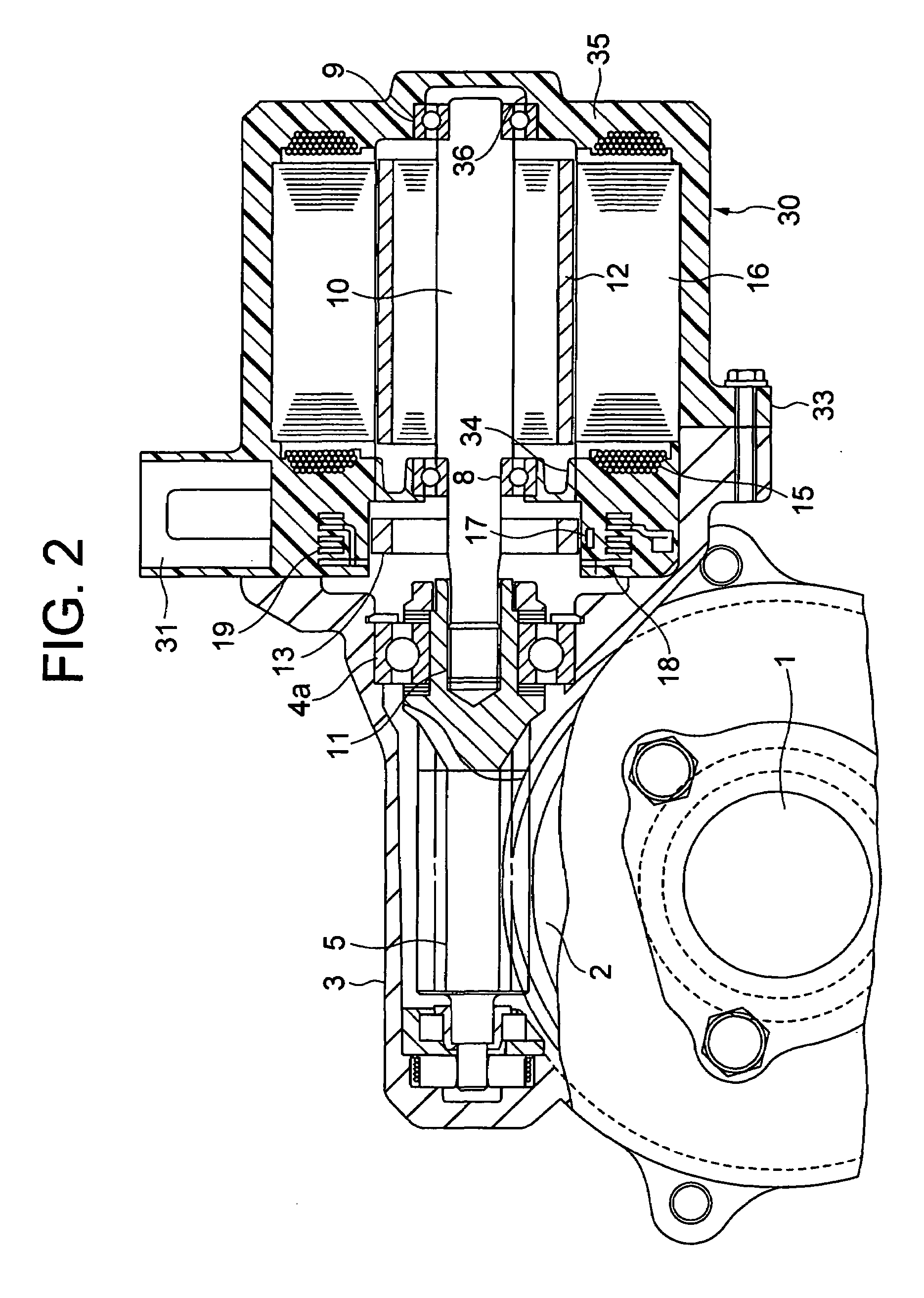
[0107]FIG. 2 is a longitudinal cross sectional view of an electric power steering apparatus according to the present invention.
[0108]As shown in FIG. 2, an output shaft 1 is linked with an input shaft (not shown), which is coupled to a steering wheel (not shown), by means of a torsion bar (not shown). A worm wheel 2 of a worm gear reduction mechanism (reduction gear) is fixedly mounted on the output shaft 1.
[0109]A worm 5 rotatably supported in a gear housing 3 by a bearing 4 etc. is in engagement with the worm wheel 2.
[0110]The rotor 10 of the brushless motor and the worm 5 are connected by means of a spline fitting portion 11 so that they are movable in the axial direction but non-rotatable relative to each other.
[0111]In the radially outer periphery of the rotor 10, there is provided a cylindrical permanent magnet for rotational driving 12 in such a way as to be opposed to a laminated core 15 that will be described later. In addition, a ring-shaped permanent magnet for sensing 13...
third embodiment
[0127]FIG. 3 is a longitudinal cross sectional view of an electric power steering apparatus according to the present invention.
[0128]In the third embodiment, a cylindrical stator 30 made of a resin is provided. The stator 30 is formed by resin molding integrally with the laminated core 16 on which a coil 15 is wound, a hall IC 17 (detection means) that detects the magnetic field of the permanent magnet for sensing (member to be detected) 13 so as to detect the rotational angle of the rotor 10, a board 18 on which the hall IC 17 is mounted, a terminal (busbar) 19 for providing connection for the coil 15 and an electric cable connection terminal (connector) 31 for a terminal connected with the coil 15 and for a terminal for outputting a signal of the hall IC 17 (detection means).
[0129]The hall IC (detection means) 17, the board 18, the terminal (busbar) 19 and the electric cable connection terminal (connector) 31 are provided in the thick-walled end portion of the stator 30 opposite t...
PUM
 Abstract
Description
Claims
Application Information
 - Generate Ideas
- Intellectual Property
- Life Sciences
- Materials
- Tech Scout
- Unparalleled Data Quality
- Higher Quality Content
- 60% Fewer Hallucinations
Browse by: Latest US Patents, China's latest patents, Technical Efficacy Thesaurus, Application Domain, Technology Topic, Popular Technical Reports.
© 2025 PatSnap. All rights reserved.Legal|Privacy policy|Modern Slavery Act Transparency Statement|Sitemap|About US| Contact US: help@patsnap.com