Method for improving the received signal to noise ratio of a laser rangefinder

a laser rangefinder and received signal technology, applied in surveying, distance measurement, instruments, etc., can solve the problems of difficult integration of high voltage, high current switching devices along with sensitive receiving circuits into compact units, and large memory requirements to be effective, so as to reduce the effect of noise components, reduce the effect of noise on the receive section, and be convenient to synchroniz

Inactive Publication Date: 2007-02-27
EXELYS
View PDF2 Cites 31 Cited by
  • Summary
  • Abstract
  • Description
  • Claims
  • Application Information

AI Technical Summary

Benefits of technology

[0005]An improved technique for a laser rangefinder includes a pulsed laser sending out a repetition of light pulses and the received signal (light pulse and noise components combined) being analyzed by continuous averaging of successive received signal discrete time sequences, each sequence beginning with the onset of transmitted laser light to reduce the effect of the noise components in the received signal.
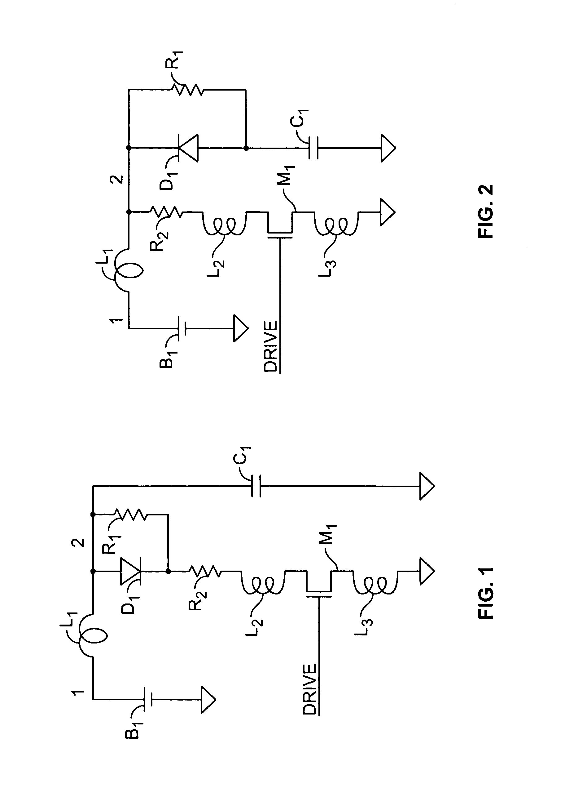
[0006]Also, a circuit is provided for generating high potentials for the laser diode driving circuitry that simultaneously drives the laser diode, having at least one of several beneficial characteristics. It is conveniently synchronous with the light pulse send / receive process to reduce the effects of noise on the receive section. It is energy efficient in converting low battery potentials to higher voltages. Finally, it utilizes a minimal number of components, leading to high product economy.

Problems solved by technology

This later technique is somewhat effective in improving the ability of the rangefinder to range more distant targets, but is computationally intensive.
It can also require a significant amount of memory to be effective.
Integrating high voltage, high current switching devices along with sensitive receiving circuits into compact units is difficult.
The generation of extremely short, high current pulses is problematic when unavoidable driving component lead inductances are considered.
Such high voltages however, in a portable, battery powered system, are typically developed through the use of a switching power supply that will also generate switching noise that is deleterious to the sensitive receive circuitry.

Method used


Image

  • Method for improving the received signal to noise ratio of a laser rangefinder
  • Method for improving the received signal to noise ratio of a laser rangefinder
  • Method for improving the received signal to noise ratio of a laser rangefinder

Examples


Embodiment Construction

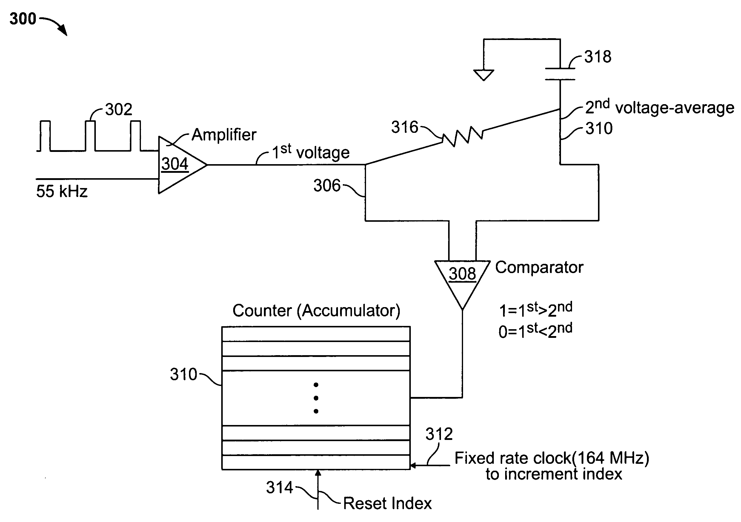
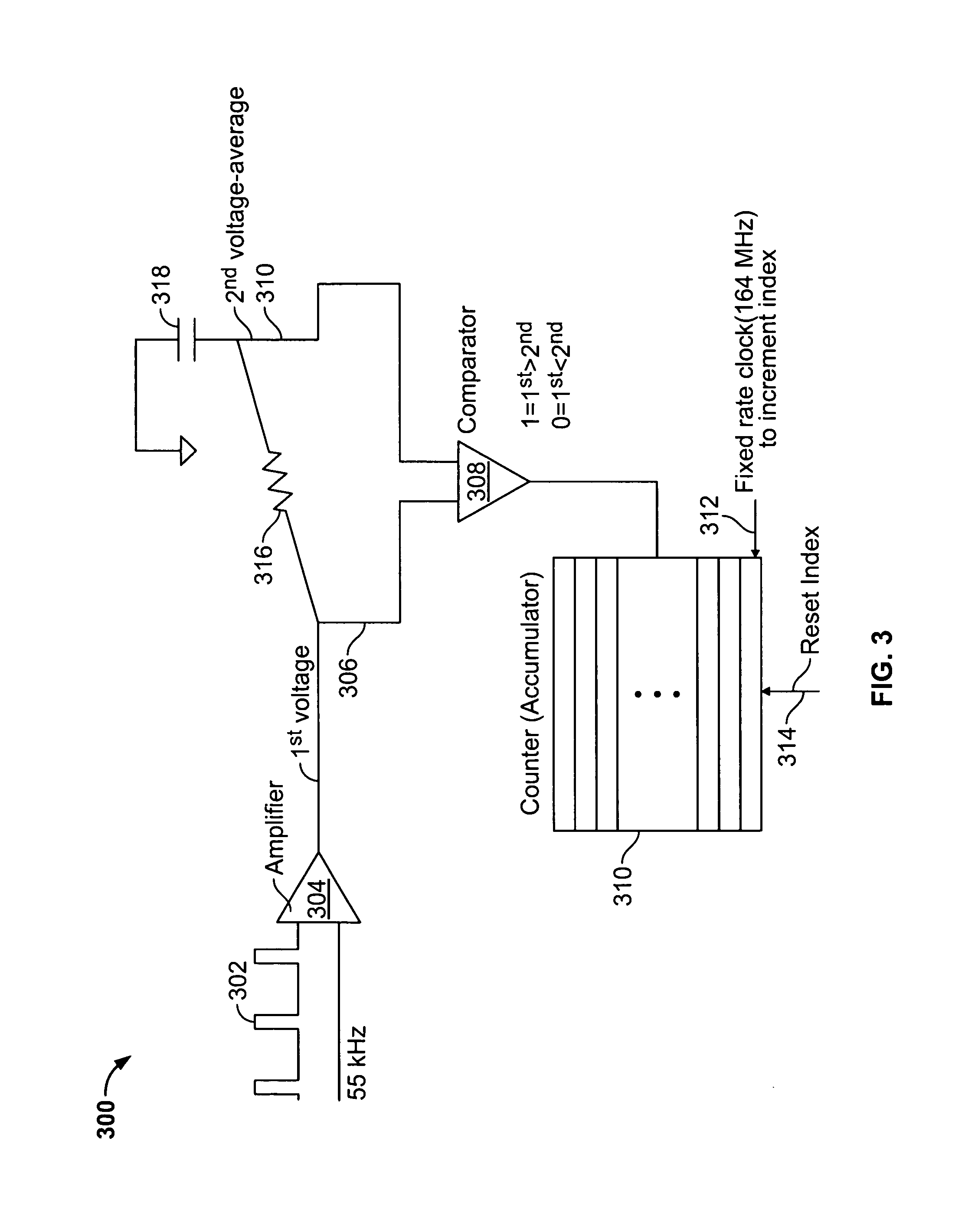
[0009]We first describe, with reference to the circuitry 300 in FIG. 3, a method to improve the signal to noise ratio of a signal received by a laser rangefinder and usable to determine a range to a target. In the FIG. 3 example, a laser is forced to emit a very brief pulse (about 10 nS long) at a rate of about 55 KHz. The laser pulse is reflected off a target, and some of the light is converted to a voltage signal 302 by a photosensor (not shown), and amplified by an amplifier 304. The output of the amplifier 304 is provided as a first voltage signal 306 to a comparator 308. The first voltage signal 306 includes unavoidable photodetector and amplifier noise. An average ambient output of the amplifier 304 provides a second voltage signal 310 to the comparator 308. For example, in the FIG. 3 circuitry, the average ambient output of the amplifier 304 is the result of an RC averaged output, where a resistor 316 is connected to the output of the amplifier 304 and a capacitor 318 is conn...


PUM


Abstract

An improved technique for a laser rangefinder includes a pulsed laser sending out a repetition of light pulses and the received signal (light pulse and noise components combined) being analyzed by continuous averaging of successive received signal discrete time sequences, each sequence beginning with the onset of transmitted laser light. Also, a circuit generates high potentials for the laser diode driving circuitry that simultaneously drives the laser diode, having at least one of several beneficial characteristics: It is conveniently synchronous with the light pulse send/receive process to reduce the effects of noise on the receive section. It is energy efficient in converting low battery potentials to higher voltages. Finally, it utilizes a minimized number of components, leading to high product economy.

Description

BACKGROUND[0001]Laser rangefinders determine the distance to a target by emitting a brief, narrow beam light pulse to a target and measuring the time for the reflected light to return. Since the speed of light in air is constant, accurate measurements can be obtained through the use of such devices. Most targets are non-reflective, absorbing some of the light and dispersing the remainder in all directions. As a result, the received light pulse is very faint and decreases as the square of the target distance. For laser rangefinders that emit ‘eye safe’ levels of energy, and have restricted receive lens areas, the received light pulse amplitude from any target over a few hundred yards in range is buried in photo detector noise.[0002]Laser rangefinders typically establish a threshold that is above the noise level, and trigger a timing circuit upon the received pulse exceeding the threshold. Alternately, the threshold is set somewhat lower (into the noise), causing numerous authentic an...

Claims


Application Information

Patent Timeline
Patent Type & Authority Patents(United States)
IPC IPC(8): G01C3/08
CPCG01S7/4861G01S17/10G01S7/4873
Inventor BARR, KEITH E.
Owner EXELYS
Why Eureka
Try Eureka