Single-phase power conversion device and three-phase power conversion device

a power conversion device and single-phase technology, applied in the direction of power conversion systems, dc-dc conversion, instruments, etc., can solve the problems of slow response of conventional dc component suppression methods using saturable reactors or the like, unavoidably large devices, and difficult to improve the accuracy of dc component correction, etc., to achieve high accuracy, prevent biased magnetization of transformers, and suppress dc components easily

Inactive Publication Date: 2007-02-27
ORIGIN ELECTRIC CO LTD
View PDF6 Cites 12 Cited by
  • Summary
  • Abstract
  • Description
  • Claims
  • Application Information

AI Technical Summary

Benefits of technology

[0044]It can be understood from above that correction to remove the DC components from the target currents for the three phases can suppress sufficiently the DC components in the line voltages in the power conversion device.
[0072]According to the present invention, a target current is generated by a target current generation means and the target current is corrected based on the asymmetry of the load current detected by the second current detection means. Therefore, there can be provided a quick-response, high-accuracy and small-size power conversion device which can suppress a DC component in AC power to be outputted therefrom without using a large part such as a reactor. According to a preferred embodiment of the present invention, even when a half wave rectification load is connected in the load via a transformer, biased magnetization of the transformer can be prevented by applying correction current in such a direction as to suppress the asymmetric current.

Problems solved by technology

However, the conventional DC component suppression method using a saturable reactor or the like has a problem of slow response since the peak values of positive-negative asymmetric excitation current flowing through the saturable reactor and reactor are detected and excitation current value in one cycle is integrated in an integration circuit to detect a DC component proportional to the amount of magnetic saturation.
Also, the accuracy in correcting of the DC component is difficult to improve because of the manufacturing variation of the saturable reactor and the reactor.
In addition, a problem arises that since the saturable reactor and the reactor are large in size, the device is unavoidably large in size.
However, there has been found a problem that a DC component is generated by thermal drift of the current loop and so on when the power conversion device is operating, and the DC component is amplified by the control means and introduced into the output from the main circuit.
In such a case, when a DC component is contained in the output from the power conversion device, defects such as biased magnetization of the transformer can occur.

Method used


Image

  • Single-phase power conversion device and three-phase power conversion device
  • Single-phase power conversion device and three-phase power conversion device
  • Single-phase power conversion device and three-phase power conversion device

Examples


first embodiment

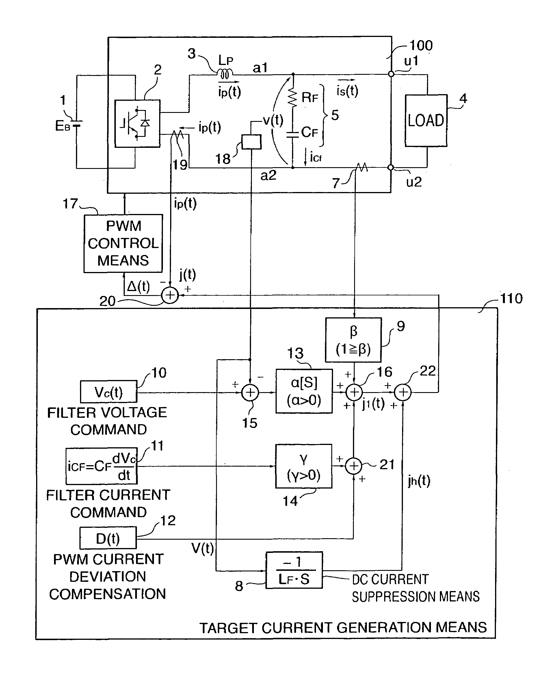
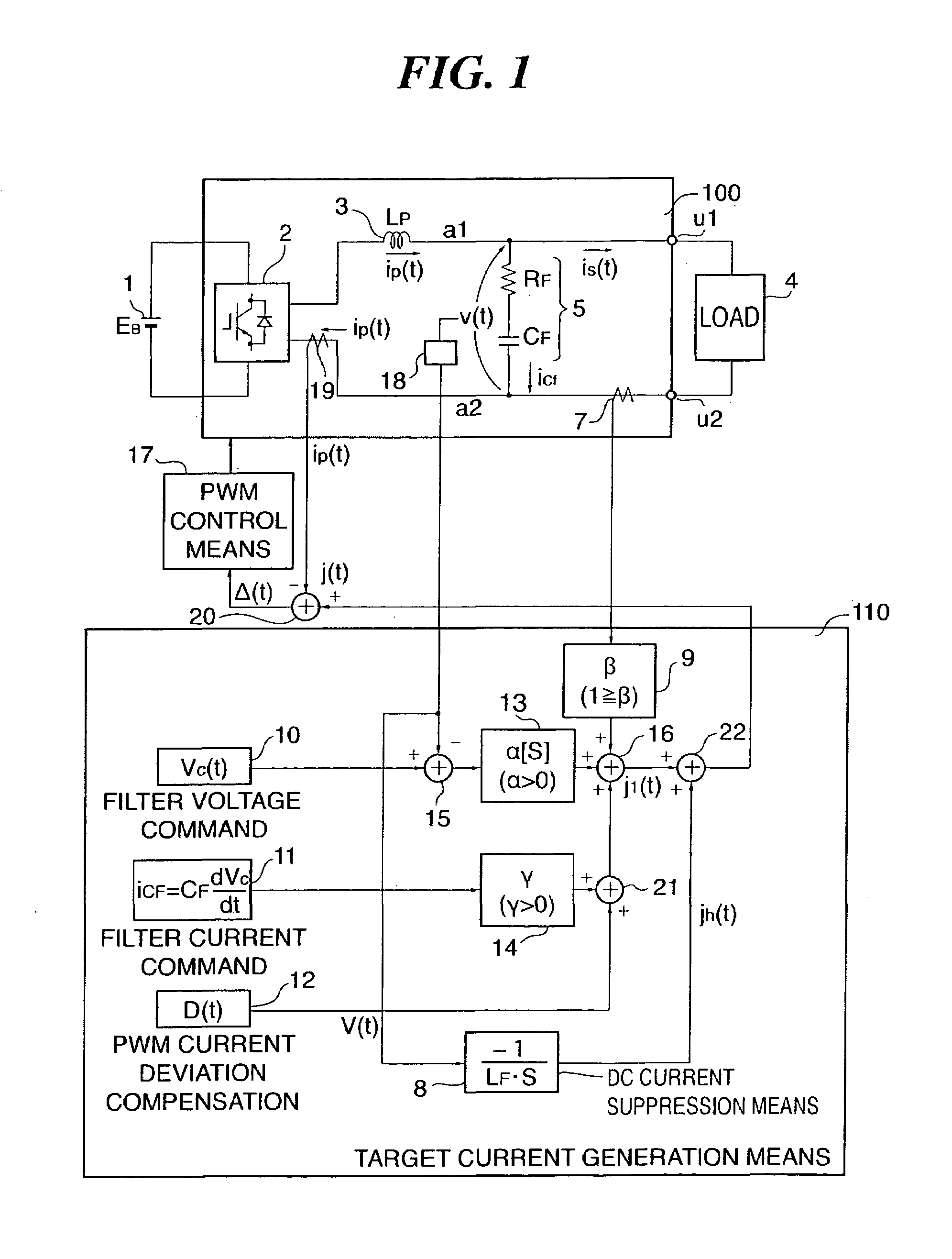
[0111]FIG. 1 shows an example of the circuit configuration of a single-phase power conversion device according to a first embodiment of the present invention. Those parts having the same functions as those in FIG. 21 are designated in FIG. 1 by the same reference numerals. The differences from the device shown in FIG. 21 are that the output from the fourth adder 16 is changed from “target current” to “first target current jl(t),” and that a DC component suppression means 8 for receiving a filter voltage v(t) as a detection signal from the voltage detection means 18 and calculating a correction amount jh(t) for a target current j(t) and a fifth adder 22 for adding the correction amount jh(t) to the first target current jl(t) and outputting the target current j(t) to a first adder 20 are added in the target current generation means 110. The correction is carried out to suppress a DC component VD in the filter voltage v(t), that is, the output terminal voltage.

[0112]That is, the power ...

second embodiment

[0122]A three-phase power conversion device as a second embodiment of the present invention is next described. The approach for suppression of DC component in a three-phase power conversion device is basically the same as that in a single-phase power conversion device. In the case of a three-phase power conversion device, correction amounts jha(t) jhb(t), and jhc(t) are calculated for correction of three target currents ja(t) jb(t), and jc(t), respectively, and a DC component suppression approach similar to that for a single-phase power conversion device is applicable.

[0123]In the three-phase power conversion device, voltage detection means 18 detect line voltages vab(t), vbc(t) and vca(t) across three output terminals u, v and w the output terminal voltage v(t). The output current ip(t) detected by first current detection means 19 has three components ipa(t), ipb(t) and ipc(t), and the load current is(t) detected by second current detection means 7 has three components isa(t), isb(...

third embodiment

[0136]FIG. 7 shows an example of the circuit configuration of a single-phase power conversion device according to a third embodiment. Those parts having the same functions as those in FIG. 1 are designated in FIG. 7 by the same reference numerals and their description is omitted. The differences from the embodiment shown in FIG. 1 are mainly described. The differences are that a DC voltage detection means 6 is interposed between the filter circuit 5 and the second current detection means 7 and a DC component VD in the output terminal voltage v(t) is detected by the DC voltage detection means 6, and that the DC component suppression means 8 receives the DC component VD in the output terminal voltage v(t) detected by the DC voltage detection means 6 instead of a filter voltage detected by the filter circuit 5 and calculates a correction amount jh(t) for the target current. The DC voltage detection means 6, which is interposed between the filter circuit 5 and the second current detecti...


PUM


Abstract

To suppress a DC component in AC power in a power converter for converting DC power to AC power. DC power is converted to AC power by a converter 2, and the AC power is supplied to output terminals u1 and u2 via an inductor 3. The converter 2 is controlled based on an error Δ(t) between an output current ip(t) outputted from the converter 2 and a target current j(t) outputted from a target current generation means 110 as a target value for the output current ip(t), and a DC component VD in an output terminal voltage v(t) is detected by a voltage detection means 18. A DC component ID is suppressed by correcting a target current j(t) by a DC component suppression means 8. Also, a DC component in the AC power is suppressed to prevent biased magnification of a transformer 4 by calculating a correction amount jh(t) for correcting the target current j(t) from the difference between a first instantaneous value d1 of a load current is(t) flowing to a load 4 at a first time point t1 and a second instantaneous value d2 of the load current is(t) at a second time point t2 that is a half cycle after the first time point to correct the target current j(t).

Description

BACKGROUND OF THE INVENTION[0001]1. Technical Field[0002]The present invention relates to a single-phase power conversion device and a three-phase power conversion device. More specifically, the present invention relates to a single-phase power conversion device and a three-phase power conversion device for converting DC power to AC power in which a DC component in the AC power is suppressed by extracting the DC component from the output terminal voltage and correcting a target current.[0003]2. Related Art[0004]Many power conversion devices have a transformer to insulate a converter thereof from a load or to make the converter output compatible with the system voltage of the load. When a DC component is introduced into the input voltage to the transformer on the load side because of temperature drift or offset in the control system, the iron core of the transformer is magnetized in one direction by the DC component, which causes uneven distribution of magnetic flux called biased mag...

Claims


Application Information

Patent Timeline
Patent Type & Authority Patents(United States)
IPC IPC(8): H02M1/12H02H7/122
CPCH02M7/53871H02M7/53875H02M2007/4803H02M7/4803
Inventor OHSHIMA, MASAAKISHIMIZU, HIROKAZUUSHIKI, SHUICHI
Owner ORIGIN ELECTRIC CO LTD
Why Eureka
Try Eureka