Apparatus for scanning optical recording media using a differential phase detection method

a technology of optical recording media and scanning apparatus, which is applied in the direction of optical discs, disposition/mounting of heads, instruments, etc., can solve the problems of incorrect determination of the phase angle of diagonal summation signals relative to one another, inability to determine the correct phase angle, and disadvantages of known apparatuses, etc., to achieve short time intervals, increase the accuracy of phase value, and increase the accuracy of track error signals

Inactive Publication Date: 2007-02-27
THOMSON LICENSING SA
View PDF10 Cites 4 Cited by
  • Summary
  • Abstract
  • Description
  • Claims
  • Application Information

AI Technical Summary

Benefits of technology

[0012]A sequence of more than two successive zero crossings in one of the diagonal summation signals without a zero crossing occurring in the other diagonal summation signal in the same period of time is regarded as an impermissible sequence according to the invention. This has the advantage that what is involved in this case is an unambiguous condition for an impermissible edge sequence. When the scanning beam crosses from one side of the track centre to the other side, two successive zero crossings occur in one diagonal summation signal without a zero crossing occurring in the other diagonal summation signal in this period of time. This is a permissible sequence; a correct track error signal is formed in this case. However, as soon as three successive zero crossings occur in one of the diagonal summation signals before a zero crossing occurs in the other diagonal summation signal, an error is present. The phase value derived therefrom is generally incorrect.
[0013]Furthermore, if a sequence of more than one pair of zero crossings occurs within a predetermined time period, a zero crossing of one diagonal summation signal and a zero crossing of the other diagonal summation signal which takes place shortly thereafter being regarded as a pair of zero crossings, it is regarded as an impermissible sequence according to the invention. This has the advantage that the accuracy of the determination of the track error signal is increased further. By way of example, when the scanning beam changes from one track to the next track of the recording medium, it happens that signal components originating from two different tracks are evaluated. Although the edges of the diagonal summation signals then apparently occur in the correct order, they nevertheless have an excessively short time interval between them. On account of the structure of the recording medium, such a short time interval cannot occur if only signal components from a single track are evaluated. In this case too, an incorrect phase angle is determined which, according to the invention, is not used for determining the track error signal.
[0014]If an accumulation of impermissible sequences occurs, then an error indication signal is generated. This has the advantage that the error indication signal indicating a specific state of the system can be derived in a simple manner. A particularly large number of impermissible sequences occur when the scanning beam is situated between two tracks. If the frequency exceeds a specific value, then a fault indication signal indicating the inter-track state is output. If the recording medium exhibits scratches or is adversely affected in some other way, characteristic accumulations of impermissible sequences likewise occur, which are detected and output as error indication signal.
[0015]The invention furthermore provides for the diagonal summation signals to be evaluated in a predetermined clock cycle. In this case, a zero crossing is detected if one of two successive values of a diagonal summation signal lies above, and the other of the said values lies below, a reference value. The temporal position of this zero crossing is interpolated using the value or values lying above and / or below the reference value. This has the advantage that the diagonal summation signals are not evaluated in an uninterrupted manner, rather digitized values can be used. Accurate determination of the phase angle is nonetheless carried out by means of the interpolation. In this case, the clock cycle and the interpolation method should be suitably coordinated with one another; if the clock signal has a large width, if appropriate a number of values before and after the zero are accordingly included in the interpolation, which is then preferably non-linear interpolation.
[0016]The phase between a zero crossing of one diagonal summation signal and a zero crossing of the other diagonal summation signal is determined from the respective interpolated value of the temporal position. If a number of complete clock cycles lie between the zero crossings, a value corresponding to the number of these clock cycles is additionally added. This has the advantage that the accuracy of the value of the phase is increased over and above the temporal resolution predetermined by the clock cycle. As a result, on the one hand, a more accurate track error signal is formed on account of the more accurate phase angle and, on the other hand, the rate at which impermissible sequences are identified is increased since the higher temporal resolution leads to a smaller number of zero crossings which are interpreted as coinciding in time.
[0017]The invention provides for the track error signal to be extrapolated in the event of an impermissible sequence of zero crossings in the diagonal summation signals. The last valid value of the track error signal is kept here in the simplest case. A linear or higher extrapolation from the last values before the impermissible sequence is likewise advantageously possible, however. During the absence of a present phase value, the track error signal assumes a value which comes close to the next calculated value to be expected. This has the advantage that no abrupt change occurs in the track error signal and, consequently, reliable tracking is ensured.

Problems solved by technology

The known apparatus may be regarded as having the disadvantage that the phase angle of the diagonal summation signals relative to one another is determined incorrectly in certain cases.
The result of this is that the track error signal assumes an incorrect value and, consequently, the tracking is not effected in an optimum manner.
In this case, it can happen that a correct phase angle cannot be determined.

Method used


Image

  • Apparatus for scanning optical recording media using a differential phase detection method
  • Apparatus for scanning optical recording media using a differential phase detection method
  • Apparatus for scanning optical recording media using a differential phase detection method

Examples


Embodiment Construction

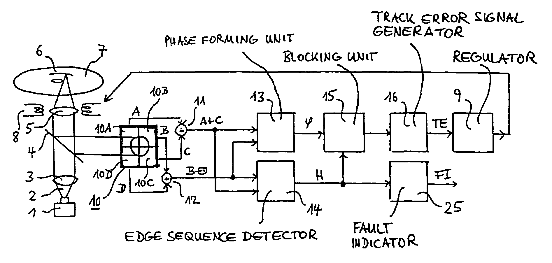
[0026]FIG. 1 shows part of an apparatus according to the invention in a schematic illustration. A laser diode 1 emits a scanning beam 2, which is concentrated by a collimator 3. After passing through a semi-transparent mirror 4, the scanning beam 2 is focused onto an information track 6 of an optical recording medium 7 by a focusing lens 5. The optical recording medium 7 is in the form of a circular disc on which there is a spiral information track 6, only a small part of which is illustrated in the figure. By means of an actuator 8, indicated as a coil here, the focusing lens 5 can be moved parallel to the direction of propagation of the scanning beam 2, for the purpose of focusing, and in the radial direction with respect to the optical recording medium 7, for the purpose of tracking. The actuator 8 is driven by a regulator 9 for this purpose.

[0027]The scanning beam 2 focused onto the information track 6 is reflected from the optical recording medium 7, passes through the focusing...


PUM

PropertyMeasurementUnit
phaseaaaaaaaaaa
phase detection methodaaaaaaaaaa
time periodaaaaaaaaaa

Abstract

An apparatus for reading from or writing to optical recording media, having a photodetector and a phase detector for detecting a phase difference between output signals of the photodetector. An object of the present invention is to propose an apparatus in which a phase signal which is as correct as possible is generated. A further object of the invention is to specify a method of which a correct track error signal is determined using a phase detection method. According to the invention, the apparatus has an edge sequence detector for detecting the sequence of edges of the output signals, and a signal blocking unit for blocking the output signal of the phase detector. In particular, the output signal of the phase detector is blocked when an impermissible sequence of zero crossings of phase detected signals.

Description

FIELD OF THE INVENTION[0001]The present invention relates to an apparatus for reading from and / or writing to optical recording media which uses a phase detection method, in particular the differential phase detection method, abbreviated to DPD method, for tracking purposes.BACKGROUND OF THE INVENTION[0002]An apparatus of this type is disclosed in EP-A2-0 822 542. It has a four-quadrant photodetector, two diagonal sum generators, which sum signals from in each case two diagonally disposed quadrants of the photodetector, and a phase forming unit, which detects a phase difference between the diagonal summation signals. This phase difference is proportional to the deviation of a light beam, scanning the tracks of a recording medium, from the track centre. It is used as the track error signal in a tracking regulating circuit.[0003]The known apparatus may be regarded as having the disadvantage that the phase angle of the diagonal summation signals relative to one another is determined inc...

Claims


Application Information

Patent Timeline
Patent Type & Authority Patents(United States)
IPC IPC(8): G11B7/00G11B7/09G11B7/133
CPCG11B7/0901G11B7/0941G11B7/0906G11B7/0948G11B7/13G11B2220/2537
Inventor BUCHLER, CHRISTIANKABUTZ, MARTEN
Owner THOMSON LICENSING SA
Why Eureka
Try Eureka