Optical disk, optical disk recording/reproduction apparatus, and optical disk signal quality evaluation method

Active Publication Date: 2007-02-27
NEC CORP +1
View PDF2 Cites 30 Cited by
  • Summary
  • Abstract
  • Description
  • Claims
  • Application Information

AI Technical Summary

Benefits of technology

[0050]In the above explanation, the data strings bk and ck have been used as an example combination of data strings that tend to be erroneously regarded. However, when the variance of the noise projected onto the error vector is to be calculated, specific data strings need not always be selected to obtain an equalization error. That is, for the calculation of the equalization error variance, a time corresponding to the data string bk need not be extracted from the data string ak used for the generation of a target signal. Instead, the equalization error obtained for

Problems solved by technology

Therefore, performing the jitter measurement is difficult.
As a result, performing the jitter measurement is difficult.
However, while restricting the intersymbol interference, the equalizer generally increases the noise component.
Thus, when the recording densi

Method used


Image

  • Optical disk, optical disk recording/reproduction apparatus, and optical disk signal quality evaluation method
  • Optical disk, optical disk recording/reproduction apparatus, and optical disk signal quality evaluation method
  • Optical disk, optical disk recording/reproduction apparatus, and optical disk signal quality evaluation method

Examples


first embodiment

[First Embodiment]

[0067]The relationship between a bit error rate (bER) and the signal quality evaluation value S is examined by a read-only optical disk (ROM disk), provided in advance by using embossing to record a pit data string on a polycarbonate substrate that is 0.6 mm thick.

[0068]In this embodiment, the pit string was formed on the substrate as random data that was modulated based on the (1-7) modulation method, and the length of a 2T pit, which is the shortest, was 0.2 μm, while in the radial direction, the interval for the pits was 0.4 μm. An optical head having a wavelength of 405 nm and a numerical aperture (NA) of 0.65 for an object lens was employed to reproduce data recorded on the ROM disk at a linear speed of 6.6 m / s and at a reproduction power of 0.5 mW (in this case, a clock cycle T is 15.15 ns). Then, the reproduced waveform was equalized to PR(12221) to measure the bit error rate bER and the signal quality evaluation value S. To measure the bit error rate bER, t...

second embodiment

[Second Embodiment]

[0078]The relationship between the bit error rate bER and the signal quality evaluation value S was examined by using a phase change optical disk formed on a 0.6 mm thick polycarbonate substrate, wherein the pitches of guide grooves were 0.68 μm. For the evaluation, while the phase change optical disk was rotated at a linear speed of 5.6 m / s, an optical head having a wavelength of 405 nm and NA=0.65 was employed to record and reproduce random data that were obtained through (1-7) modulation at a clock frequency of 64.6 MHz (clock cycle of 15.48 ns). As well as in the first embodiment, the PR equalization was PR(12221). The random data were overwritten twenty times, using a recording power of 6 mW and an erasing power of 2.5 mW, and then, the signal quality evaluation value S and the bit error rate bER were measured while the focus offset value was changed. As well as in the first embodiment, the recording was performed for up to a maximum five repetitions of 2T, a...

third embodiment

[Third Embodiment]

[0085]A third embodiment for calculating the signal quality evaluation value S will now be described.

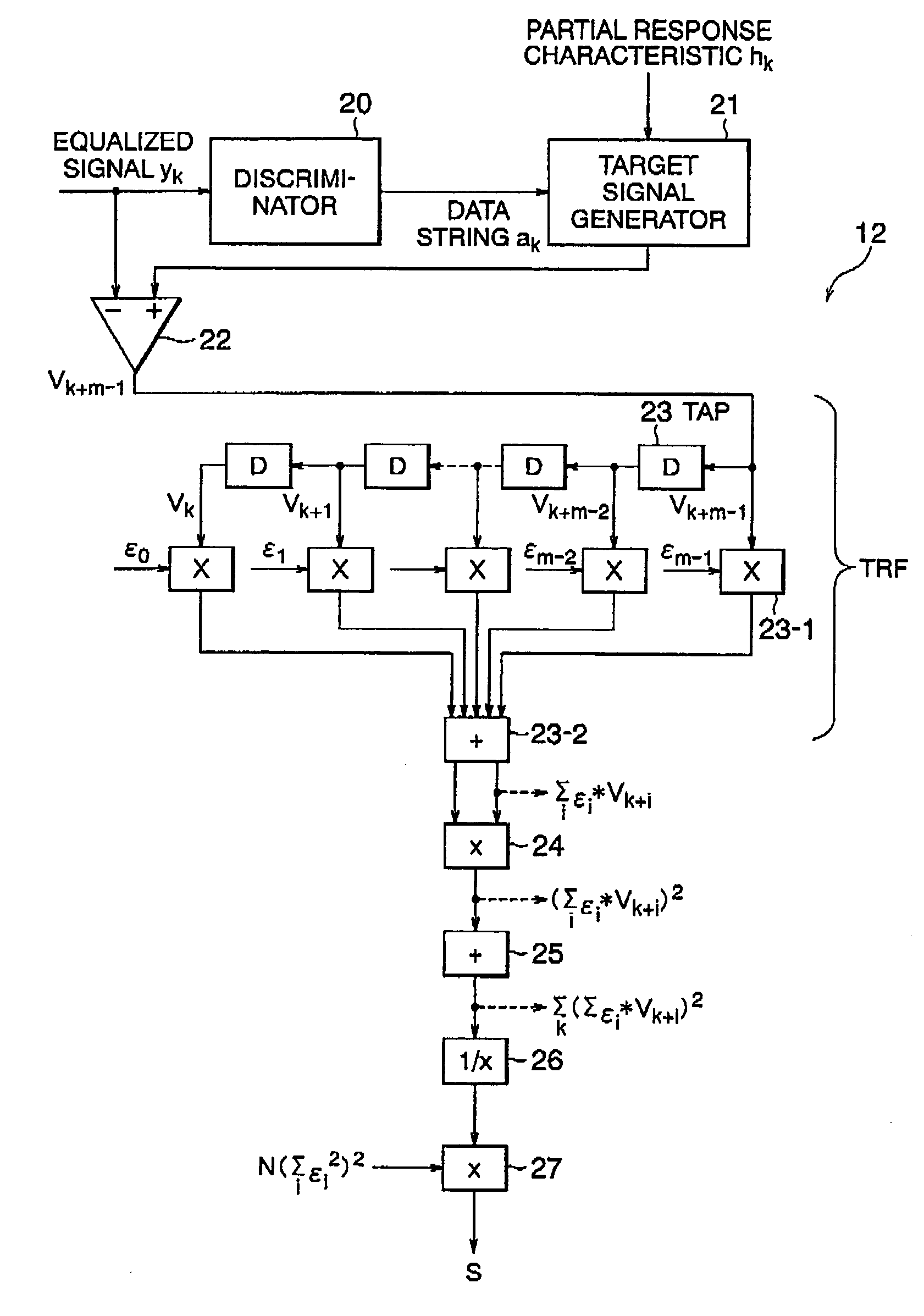
[0086]By employing Σ(vk+2vk+1+2vk+2+2vk+3+vk+4)2=N×(14R0+24R1+16R2+8R3+2R4), wherein Ri=Σvkvk+j / N is defined, the first signal quality evaluation value S1 for the first or the second embodiment can also be represented by the following equation (12):

[0087]S1=⁢14×1414⁢R0+24⁢R1+16⁢R2+8⁢R3+2⁢R4=⁢14R0+(12⁢R1+8⁢R2+4⁢R3+R4) / 7(12)

Similarly, the second signal quality evaluation value S2 and the third signal quality evaluation value S3 can also be represented by the following equations (13) and (14):

[0088]S2=⁢12×1212⁢R0+16⁢R1+2⁢R2-8⁢R3-12⁢R4-8⁢R5-2⁢R6=⁢12R0+(8⁢R1+R2-4⁢R3-6⁢R4-4⁢R5-R6) / 6(13)S3=⁢12×1212⁢R0+16⁢R1+4⁢R2+2⁢R4+8⁢R5+12⁢R6+8⁢R7+2⁢R8=⁢12R0+(8⁢R1+2⁢R2+R4+4⁢R5+6⁢R6+4⁢R7+R8) / 6(14)

[0089]Ri corresponds to the autocorrelation of an qualization error, and it is understood that when the values other than R0 are 0, the characteristic of the equalization error is white, The same...


PUM


Abstract

In order to evaluate the quality of a signal recorded on an optical recording medium, a target signal is obtained based on a predetermined data string and a predetermined partial response characteristic, and for each clock cycle, an equalization error is calculated that is a difference between the target signal and a signal reproduced each clock cycle. Further, the product of the equalization errors calculated at different times is obtained, and based on the obtained product, the quality of a signal is evaluated.

Description

BACKGROUND OF THE INVENTION[0001]1. Field of the Invention[0002]The present invention relates to an optical disk, an optical disk recording / reproduction apparatus, and a method for evaluating optical data of the optical disk.[0003]2. Related Background Art[0004]Optical disks are classified into two types: read-only optical disks on which data are recorded in advance and optical disks on which data can be recorded. To record data on the read-only optical disk, generally, an exposure process called a mastering process is performed to form embossments (physically raised and recessed conditions) on the optical disk. Then, to record data on the recordable optical disk, the optical disk is irradiated with a focused laser beam to change a specific physical characteristic of a recording film.[0005]Conventionally, when evaluating the quality of data or signals recorded on an optical disk, a measurement is generally made of the jitter characteristic of a reproduction signal that is obtained b...

Claims


Application Information

Patent Timeline
IPC IPC(8): G11B5/09G11B7/004G11B20/10G11B20/18G11B27/36
CPCG11B20/10009G11B20/10055G11B20/1012G11B20/10296G11B2220/218G11B2220/20G11B2220/216
Inventor OHKUBO, SHUICHIHONMA, HIROMIOGAWA, MASATSUGUNAKANO, MASAKIIWANAGA, TOSHIAKIKASHIHARA, YUTAKANAGAI, YUUJI
Owner NEC CORP
Why Eureka
Try Eureka