System for synchronizing first and second sections of data to opposing polarity edges of a clock

a technology of synchronizing first and second sections of data and clocks, applied in the field of data interfacing, can solve the problems of limiting the approaches available and wasting months of valuable design tim

Active Publication Date: 2007-02-27
EXTREME NETWORKS INC
View PDF5 Cites 13 Cited by
  • Summary
  • Abstract
  • Description
  • Claims
  • Application Information

AI Technical Summary

Problems solved by technology

One challenge which is encountered when attempting to communicate DDR or QDR® data between a sender and receiver of such data is synchronizing the data on both edges of the clock when many edge-triggered devices useful for synchronization, such as flip flops and the like, only transition on one or the other but not both of the rising or falling edges of the clock.
The problem is compounded because the use of edge-triggered devices of both polarities may not always be possible, and the asymmetry typically exhibited between the positive and negative portions of the clock may further limit the approaches available.
Another challenge is achieving compatibility with the different senders and receivers of data that may be encountered.
Another challenge is providing an interface which has the flexibility to handle unexpected circuit board layout constraints which are ever increasing due to increasing complexity and higher operating frequencies.
During the circuit board design process, if the interface is inflexible, and an unexpected circuit board layout constraint is encountered which cannot be accommodated by the interface, either the circuit board layout or the interface may need to be retooled, potentially wasting months of valuable design time.

Method used


Image

  • System for synchronizing first and second sections of data to opposing polarity edges of a clock
  • System for synchronizing first and second sections of data to opposing polarity edges of a clock
  • System for synchronizing first and second sections of data to opposing polarity edges of a clock

Examples


Embodiment Construction

[0055]As utilized herein, terms such as “about” and “substantially” and “near” are intended to allow some leeway in mathematical exactness to account for tolerances that are acceptable in the trade. Accordingly, any deviations upward or downward from the value modified by the terms “about” or “substantially” or “near” in the range of 1% to 20% or less should be considered to be explicitly within the scope of the stated value.

[0056]As used herein, the term “software” includes source code, assembly language code, binary code, firmware, macro-instructions, micro-instructions, or the like, or any combination of two or more of the foregoing.

[0057]The term “memory” refers to any processor-readable medium, including but not limited to RAM, ROM, EPROM, PROM, EEPROM, disk, floppy disk, hard disk, CD-ROM, DVD, or the like, or any combination of two or more of the foregoing, on which may be stored a series of software instructions executable by a processor.

[0058]The terms “processor” or “CPU” ...


PUM


Abstract

Systems of and methods for processing data for communication between a sender and a receiver are described. In one embodiment, the phase of a first clock is used to select between first and second portions of data from the sender. The selected data is then synchronized, for communication to the receiver, to a second clock having a frequency which is an integer multiple of that of the first clock, wherein the integer multiple is two or more. The first and second portions of the data may be provided to the same output pins in this embodiment for communication to the receiver. In a second embodiment, first and second portions of data from the sender are clocked in using first and second edges, respectively, of a first clock. The first and second edges have a first polarity if a first pre-determined mode is in effect, and have a second polarity if a second pre-determined mode is in effect. Data derived from the clocked in data is then synchronized, for communication to the receiver, to a second clock. In a third embodiment, data from the sender is clocked in using a first clock. The clocked in data is then transformed responsive to a pre-determined mode selected from a plurality of possible modes. The transformed data is then synchronized, for communication to the receiver, to a second clock. In a fourth embodiment, a first clock is provided which is delayed relative to a second clock by a pre-determined amount. Data is then clocked out for communication to a receiver using the second clock, and clocked in for communication back to the sender using a third clock derived from the second clock. Data derived from the clocked in data is then synchronized to the first clock.

Description

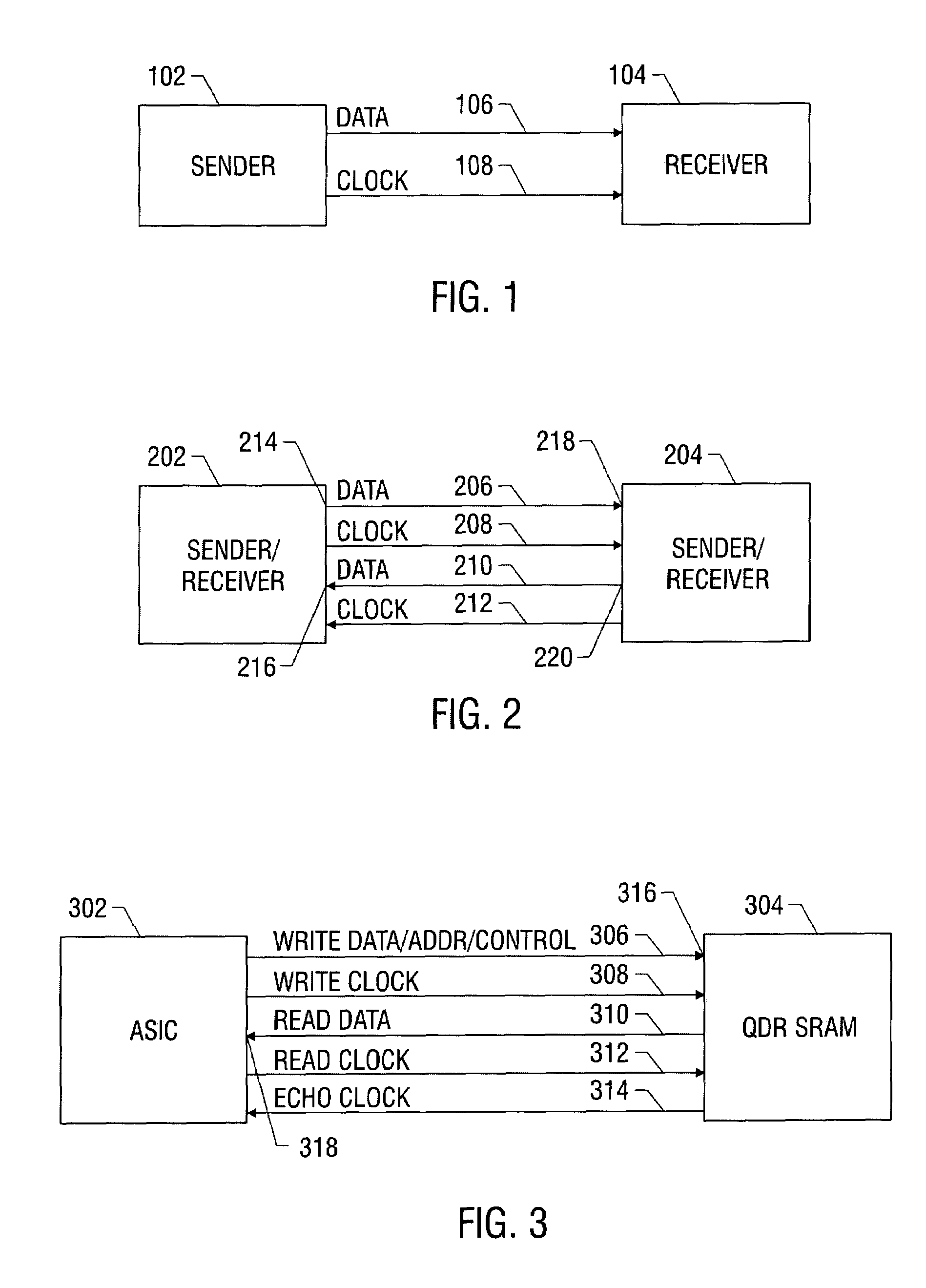
1. FIELD OF THE INVENTION[0001]This invention relates to the field of data interfacing, and, more specifically, to a data interface providing for the communication of source synchronous data between a sender and a receiver of such data.2. RELATED ART[0002]Source synchronous data is data which is transmitted in conjunction with a clock to which it is synchronized. FIG. 1 illustrates source synchronous data 106 communicated between a sender 102 and a receiver 104 of the data. As illustrated, the data is accompanied by a clock 108 to which it is synchronized.[0003]The data may be uni-directional or it may be bi-directional. FIG. 1 illustrates uni-directional communication of source synchronous data. FIG. 2 illustrates bi-directional communication of source synchronous data between sender / receiver 202 and sender / receiver 204. The data from sender / receiver 202 to sender / receiver 204 is identified with numeral 206 and is accompanied by clock 208. The data from sender / receiver 204 to sende...

Claims


Application Information

Patent Timeline
Patent Type & Authority Patents(United States)
IPC IPC(8): G06F1/12
CPCG06F5/06
Inventor BHANDARI, NITINSWENSON, ERIK R.YOUNG, CHRISTOPHER J.
Owner EXTREME NETWORKS INC
Why Eureka
Try Eureka