Wind energy conversion device

a wind energy and conversion device technology, applied in the direction of electric generator control, rotors, machines/engines, etc., can solve the problems of affecting affecting the operation of wind generators, and devices subject to variations in wind speed, so as to improve overspeed protection, reduce noise, and reduce the electrical output of wind generators

Inactive Publication Date: 2007-03-06
EJB LLC
View PDF16 Cites 67 Cited by
  • Summary
  • Abstract
  • Description
  • Claims
  • Application Information

AI Technical Summary

Benefits of technology

[0022]The wind resisted offset arrangement is particularly useful in the event that the normal electrical load is lost due to an accident, an electrical system malfunction, or interruption of a utility connection. The propeller rotational velocity in this event is higher than normal for all wind speeds. Conversely, at any given rotational speed the wind pressure is less, as compared to pressure under normal load conditions. As a result, the blade tip airfoil sections begin to pitch at a lower rpm. The earlier blade pitching beneficially reduces noise and provides improved overspeed protection under load loss conditions. This feature also is useful in battery charging systems, because it enables reduction of the electrical output of a wind generator in a charging system when the battery becomes fully charged, without unduly increasing aerodynamic noise.
[0023]

Problems solved by technology

Devices and systems for converting wind energy frequently are used to supplement the electric power available over power transmission lines, and may be the sole source of electric power in remote areas where electrical power transmission is impractical or impossible.
All of these devices are subject to variations in wind velocity.
However, given that the force due to wind increases in proportion to the cube of the wind speed, high wind speeds even if only occasional or momentary can damage system components.
Larger propellers also give rise to con

Method used


Image

  • Wind energy conversion device
  • Wind energy conversion device
  • Wind energy conversion device

Examples


Embodiment Construction

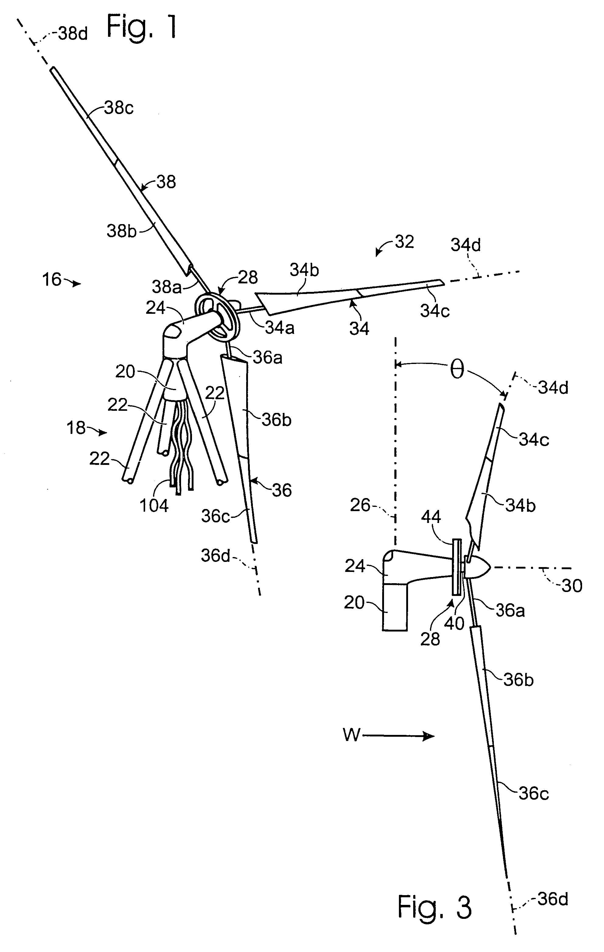
[0039]Turning now to the drawings, there is shown in FIG. 1 a wind energy conversion device 16 constructed according to the present invention. The device is supported on a tower 18 in the form of an open frame that provides stationary support for the power generating components. The tower includes a vertical sleeve 20 and legs 22 extending upwardly from the ground or foundation (not shown) to the sleeve. Horizontal or inclined cross bracing members (not shown) are coupled between the legs to stabilize tower 18. The height of tower 18 depends on the size of the propeller, and on factors such as topography and proximity of trees and other obstructions to the wind. In one preferred version of device 16, involving a propeller diameter of 20 feet, the tower height can range from about 40 feet to about 140 feet.

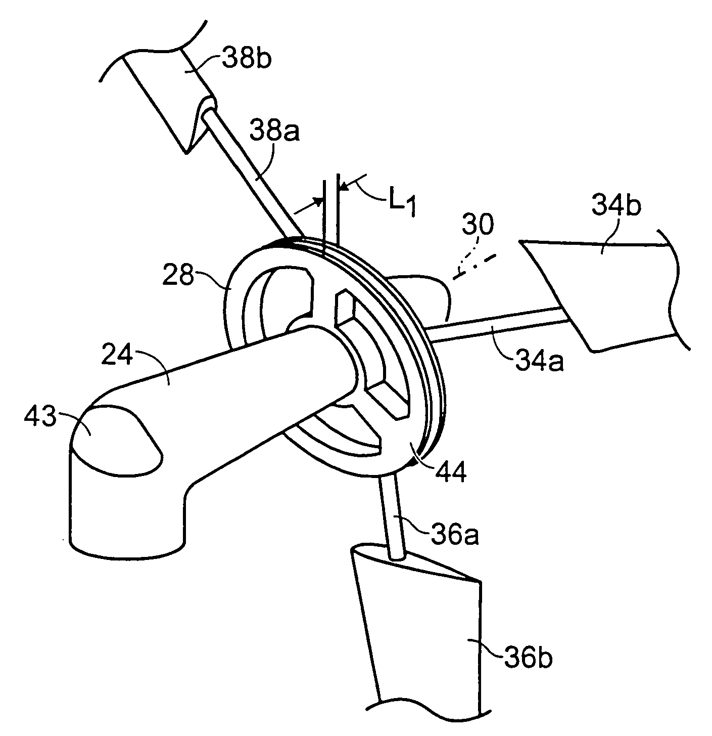
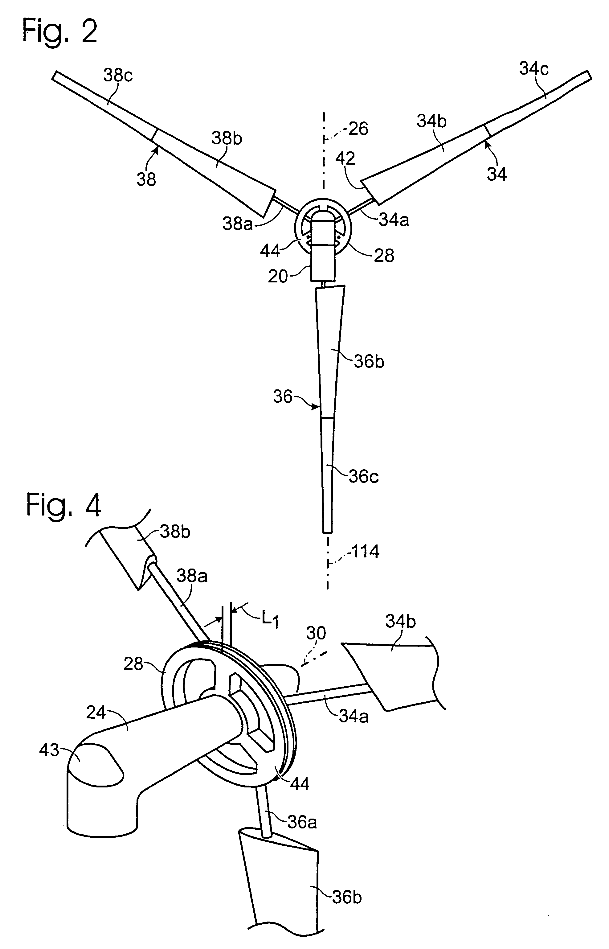
[0040]A propeller mounting structure including a shroud 24 is mounted at the top of the tower, to pivot about a substantially vertical yaw axis 26 (FIG. 2). The propeller mounting ...


PUM


Abstract

A wind energy conversion device includes a propeller in which each of the propeller blades includes a proximal (radially inward) non-airfoil mounting section, a medial section and a distal tip section mounted to pivot relative to the medial section about a pitch axis running lengthwise of the blade. At low wind speeds, each tip section and its associated medial section cooperate to provide a single airfoil. When the propeller rpm exceeds a predetermined threshold, each of the tip sections begins to pivot toward a full governing position, which tends to reduce the propeller rpm. To permit wind tracking, the device is mounted to pivot on a vertical axis. The propeller blades are downwind of the vertical axis, and slightly inclined to define a cone diverging in the downwind direction. The electrical power generating components are located upwind of the propeller and centered about the propeller axis, and have a radius less than the length of the proximal blade sections. Forming the airfoil component of the blade in several sections (medial section, tip section and further sections as desired) facilitates fabrication by injection molding.

Description

BACKGROUND OF THE INVENTION[0001]The present invention is directed to systems and devices for converting wind energy into electrical power, and more particularly to governing mechanisms to provide overspeed protection and power regulation for such systems and devices, and also to features for improving the efficiency and wind tracking and power regulation capability of these systems and devices.[0002]Wind energy conversion systems continue to gain favor as lower cost and more environmentally sound alternatives to more centralized methods of generating electricity. Devices and systems for converting wind energy frequently are used to supplement the electric power available over power transmission lines, and may be the sole source of electric power in remote areas where electrical power transmission is impractical or impossible. In addition to generating electrical power, wind conversion devices also are used to provide direct mechanical power via gear trains and other mechanisms driv...

Claims


Application Information

Patent Timeline
IPC IPC(8): F03D7/04F03D7/02F03D9/00
CPCF03D7/0248F03D9/002H02K7/1838F05B2220/7066Y02E10/725F05B2240/302Y02E10/721Y02E10/723F03D9/25Y02E10/72
Inventor BAYLY, ELLIOTT
Owner EJB LLC
Why Eureka
Try Eureka