Cooling system for a platform of a turbine blade

a cooling system and turbine blade technology, applied in the field of turbine blades, can solve the problems of reducing the useful affecting the service life so as to reduce the likelihood of cracking of the turbine blade, reduce the stress, and increase the cooling capacity of the internal cooling system.

Inactive Publication Date: 2007-03-06
SIEMENS ENERGY INC
View PDF17 Cites 31 Cited by
  • Summary
  • Abstract
  • Description
  • Claims
  • Application Information

AI Technical Summary

Benefits of technology

[0008]An advantage of this invention is that the ribs protruding from a bottom surface of the platform act as fins by increasing the surface area upon which convection can occur, thereby increasing the cooling capacity of the internal cooling system of the turbine blade.
[0009]Another advantage of this invention is that the configuration of the platform cooling system reduces stress and as a result, reduces the likelihood of cracking of the turbine blade.

Problems solved by technology

In addition, turbine blades often contain cooling systems for prolonging the life of the blades and reducing the likelihood of failure as a result of excessive temperatures.
However, centrifugal forces and air flow at boundary layers often prevent some areas of the turbine blade from being adequately cooled, which results in the formation of localized hot spots.
Localized hot spots, depending on their location, can reduce the useful life of a turbine blade and can damage a turbine blade to an extent necessitating replacement of the blade.
During operation, the pressure of the cooling system in the turbine blade dead rim cavity is higher than the pressure on the external side of the turbine blade, which induces high leakage flow around the turbine blade attachment region and thus causes inefficient operation.
This configuration produces unacceptably high stress levels in the platform and thus, yields a short blade useage life, which is due primarily to the large mass of turbine blade material at the front and back of the blade attachment and due to the transverse orientation of the cooling channels relative to the primary stress field.

Method used


Image

  • Cooling system for a platform of a turbine blade
  • Cooling system for a platform of a turbine blade
  • Cooling system for a platform of a turbine blade

Examples


Embodiment Construction

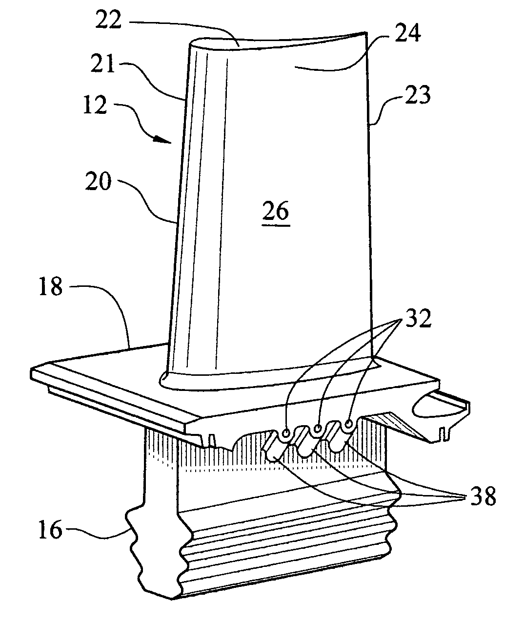
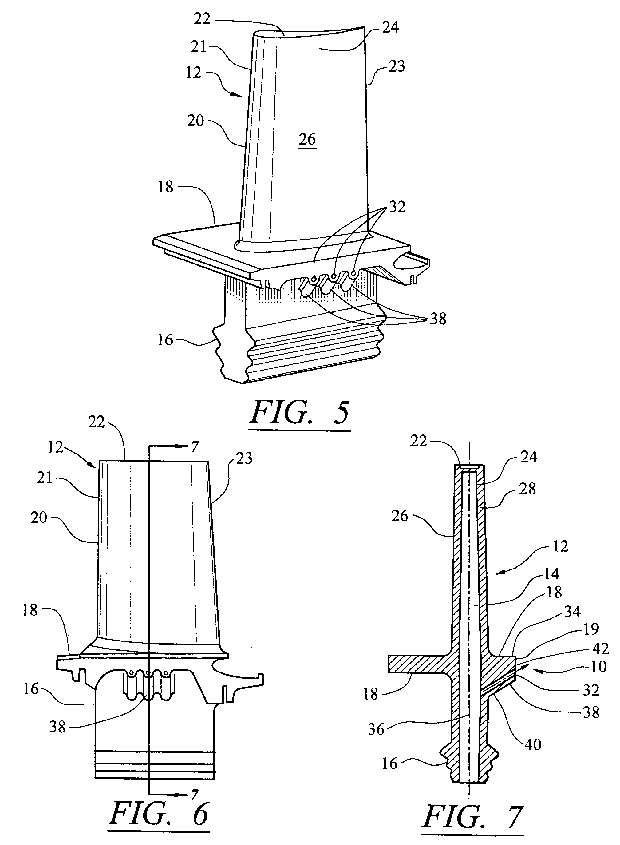
[0020]This invention is directed to a turbine blade cooling system 10 for turbine blades 12 used in turbine engines, as shown in FIGS. 5–8. In particular, turbine blade cooling system 10 is directed to a platform cooling system 10 located in a platform 18, as shown in FIGS. 5–8, extending between a cooling cavity 14 and an outer surface 19 of the platform 18 for removing heat from the platform during operation of a turbine engine in which the turbine blade 12 is positioned.

[0021]As shown in FIG. 5, the turbine blade 12 may be formed from a root 16 having a platform 18 and a generally elongated blade 20 coupled to the root 16 at the platform 18. The turbine blade 12 may have a leading edge 21 and a trailing edge 23. The turbine blade 12 may also include a tip 22 at an end of the elongated blade 20 generally opposite the root 16 and the platform 18. The elongated blade 20 may be formed from an outer wall 24 adapted for use in a turbine engine 12, for example, in a first stage of an ax...


PUM


Abstract

A turbine blade for a turbine engine having a platform cooling system formed from one or more platform cooling channels extending from an inner cooling cavity in a root of a turbine blade to an outer surface of a platform on the turbine blade. The platform cooling channels may be positioned in ribs protruding from a bottom surface of the platform. The ribs act as fins during operation of a turbine engine in which the turbine blade is installed by increasing surface area of the platform and thereby increasing convection on the bottom surface.

Description

FIELD OF THE INVENTION[0001]This invention is directed generally to turbine blades, and more particularly to hollow turbine blades having internal cooling channels for passing cooling fluids, such as air, through the cooling channels to cool the blade platform.BACKGROUND[0002]Typically, gas turbine engines include a compressor for compressing air, a combustor for mixing the compressed air with fuel and igniting the mixture, and a turbine blade assembly for producing power. Combustors often operate at high temperatures that may exceed 2,500 degrees Fahrenheit. Typical turbine combustor configurations expose turbine blade assemblies to these high temperatures. As a result, turbine blades must be made of materials capable of withstanding such high temperatures. In addition, turbine blades often contain cooling systems for prolonging the life of the blades and reducing the likelihood of failure as a result of excessive temperatures.[0003]Typically, turbine blades are formed from a root ...

Claims


Application Information

Patent Timeline
Patent Type & Authority Patents(United States)
IPC IPC(8): F01D5/30
CPCF01D5/18F05B2240/801F05D2240/81
Inventor LIANG, GEORGE
Owner SIEMENS ENERGY INC
Why Eureka
Try Eureka