Systems and methods for measuring a parameter of a landfill including a barrier cap and wireless sensor systems and methods

a technology of wireless sensor and landfill, applied in the direction of electric signalling details, electromagnetic radiation sensing, instruments, etc., can solve the problems of chloride corroding the reinforcing steel rebar in the concrete bridge deck, the structural integrity of the bridge degrades with time, and the wires present obstacles to heavy equipmen

Inactive Publication Date: 2007-03-06
BATTELLE ENERGY ALLIANCE LLC
View PDF20 Cites 64 Cited by
  • Summary
  • Abstract
  • Description
  • Claims
  • Application Information

AI Technical Summary

Benefits of technology

[0014]More particularly, some aspects of the invention provide a low power sensor platform used for periodic, remote sensing of environmental variables such as subsurface volumetric moisture, temperature, pressure, and water potential, contamination, and / or radiation. The sensor platform supports multiple sensors. The specific target for this technology is long term monitoring of landfill barrier caps. The key characteristic of the platform architecture is that all platform components are inactive until energized by a remote power source, thus no internal power source such as a battery is required. Another characteristic is that the platform communicates via short-range telemetry, i.e., no wires need penetrate to the subsurface or through a barrier. This is useful when it is desirable to avoid having wires penetrate a barrier or where subsurface sensors need to be protected from surface environmental hazards such as lightning strikes or vandalism. Other significant attributes include the potential for a long service life and a compact size that makes it well suited for retrofitting existing structures.

Problems solved by technology

The wires present obstacles to heavy equipment at the time of cap (barrier) construction, and subsequent cap maintenance.
For example, structural integrity of a bridge degrades with time due to environmental conditions.
Such oxidation may be due to direct exposure of a bridge structure to harmful material such as chlorides in the salts or it may be due to slow infiltration of chlorides into reinforced concrete sections.
Chlorides can corrode the reinforcing steel rebar in concrete bridge decks, requiring regular maintenance to ensure the health and safety of bridges.
Although the diffusion rate of chlorides may be slow, the resulting corrosion can expand the volume of reinforcing bars (rebars) of the structure and cause the surrounding concrete to crack.
Detection of corroding rebar in concrete may be difficult, and efforts to remedy such corrosion may be difficult without performing extensive rebuilding of the structure.
Acquiring knowledge as to when and where to perform such maintenance has typically been a costly and time-consuming process.
Current methods for analyzing the levels of chlorides in bridge decks involve extracting concrete core samples and analyzing them in a laboratory setting, which is laborious and time consuming.
Many tests are required, since it typically takes several years for critical chloride concentration levels to be reached.
Accordingly, monitoring costs to identify deterioration of bridge structures can be significant.

Method used


Image

  • Systems and methods for measuring a parameter of a landfill including a barrier cap and wireless sensor systems and methods
  • Systems and methods for measuring a parameter of a landfill including a barrier cap and wireless sensor systems and methods
  • Systems and methods for measuring a parameter of a landfill including a barrier cap and wireless sensor systems and methods

Examples


Embodiment Construction

[0022]This disclosure of the invention is submitted in furtherance of the constitutional purposes of the U.S. Patent Laws “to promote the progress of science and useful arts” (Article 1, Section 8).

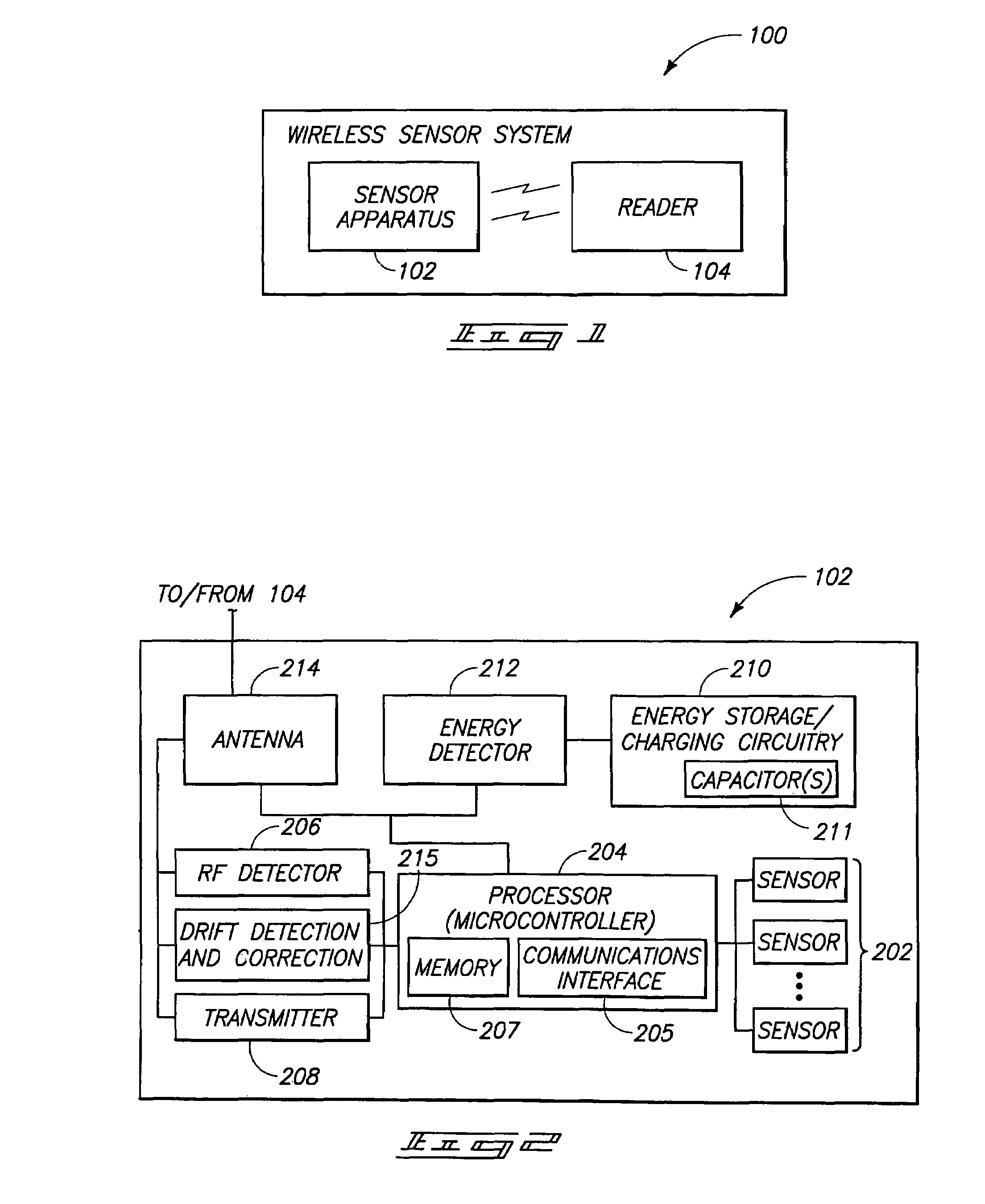
[0023]Referring to FIG. 1 a high-level block diagram of a wireless sensor system arranged according to some embodiments is shown. The depicted sensor system 100 includes a sensor platform, apparatus, or assembly 102 and a reader 104. The sensor platform 102 may be alternatively referred to as a sensor platform or sensor assembly. The reader 104 may be coupled to a local or remote device or computer or data logger. In alterative embodiments, the reader 104 includes a data logger.

[0024]In one exemplary embodiment, the sensor platform 102 is configured to be passive (e.g., inactive state or inactive mode) until it is energized by the reader 104. For purposes of this application, “passive” is defined as “not having an on-board power source.” Further details of the sensor platform 102 are desc...


PUM

PropertyMeasurementUnit
frequencyaaaaaaaaaa
frequenciesaaaaaaaaaa
diameteraaaaaaaaaa

Abstract

A method of measuring a parameter of a landfill including a cap, without passing wires through the cap, includes burying a sensor apparatus in the landfill prior to closing the landfill with the cap; providing a reader capable of communicating with the sensor apparatus via radio frequency (RF); placing an antenna above the barrier, spaced apart from the sensor apparatus; coupling the antenna to the reader either before or after placing the antenna above the barrier; providing power to the sensor apparatus, via the antenna, by generating a field using the reader; accumulating and storing power in the sensor apparatus; sensing a parameter of the landfill using the sensor apparatus while using power; and transmitting the sensed parameter to the reader via a wireless response signal. A system for measuring a parameter of a landfill is also provided.

Description

CROSS REFERENCE TO RELATED APPLICATIONS[0001]This application is a continuation-in-part of U.S. patent application Ser. No. 10 / 803,517, filed Mar. 17, 2004, by inventors Dennis C. Kunerth, John M. Svoboda, James T. Johnson, L. Dean Harding, and Kerry M. Klingler, entitled, “Wireless Sensor Systems and Methods, and Methods of Monitoring Structures”.GOVERNMENT RIGHTS[0002]This invention was made with Government support under Contract No. DE-AC07-99ID13727 between Bechtel BWXT Idaho, LLC and the U.S. Department of Energy. The Government has certain rights in the invention.TECHNICAL FIELD[0003]Aspects of the invention relate to wireless sensor systems and methods. Aspects of the invention also relate to sensing of subsurface environmental variables.BACKGROUND OF THE INVENTION[0004]Many government and public entities have landfill sites that need to be remediated. The solution for many of these sites is in-place containment using low permeability layers, barriers, or capillary barriers t...

Claims


Application Information

Patent Timeline
Patent Type & Authority Patents(United States)
IPC IPC(8): G08C19/06B09B1/00B60Q1/00G01L19/08G01M5/00G06K7/10
CPCG01L19/083G06K19/0717G01M11/30G01M5/00
Inventor KUNERTH, DENNIS C.SVOBODA, JOHN M.JOHNSON, JAMES T.
Owner BATTELLE ENERGY ALLIANCE LLC
Why Eureka
Try Eureka