Polarized optical probes

a technology of optical probes and fiberoptic probes, applied in the direction of optical radiation measurement, instruments, polarisation-affecting properties, etc., can solve the problems of inability to bring analytical instruments to the sample, limited physical access to the sample, and historically limited polarization detection of fiberoptic probes. , to achieve the effect of high degree of cross-polarization

Inactive Publication Date: 2007-03-06
OPTIMUM TECH
View PDF2 Cites 41 Cited by
  • Summary
  • Abstract
  • Description
  • Claims
  • Application Information

AI Technical Summary

Problems solved by technology

In a number of these applications, physical access to the sample is limited.
For many of these applications, it is not possible to bring the analytical instrument to the sample.
Implementing polarized detection in fiberoptic probes has historically had its limitations.
There are several design difficulties in trying to make small-diameter PESS probes suitable for certain applications, especially in the medical field for needle- or endoscopic-delivery in-vivo.
Achieving high contrast detection of two polarization modes over broad passbands is the principal challenge.
If the channels are constructed using conventional optical fiber, polarization is lost, invalidating the measurement.
While polarization-maintaining fibers exist, they only offer acceptable performance over a maximum passband on the order of 20 nm.
They are thus unsuitable for optical analysis methods employing broadband light.
Nevertheless, this approach presents a number of difficulties.
This puts further constraints on the size and shape of the polarizers, as well as the fibers.
If the probe is reusable, the manufacturing cost can be higher, but the probe must withstand high temperature sterilization by steam autoclave.
This puts additional constraints on materials, adhesives and coatings.
None of the conventional polarizer technologies has the necessary characteristics for this application.
However, placing a tiny cube at the sample end of a small diameter probe presents several difficulties.
This makes its use infeasible in certain applications, especially certain parts of the body.
This complicates the design and increases the probe size further; probes using dielectric thin film cube beamsplitters are typically in the range of 1″–4″ in diameter.
Third, in order to prevent Fresnel reflections from the sample side of the beamsplitter cubes, those optical surfaces must either be tilted or coated with a high efficiency anti-reflection coating, further increasing complexity and cost.
The use of cube beamsplitters thus does not lead to a commercially-viable probe manufacturing cost in any volume
However, there are several problems with using dichroic polarizers for fiberoptic probes.
First, none of the organic compounds used in these polarizers remain stable when exposed to the temperatures required for steam autoclave (>120° C.).
Since steam autoclaving is the most common method of sterilizing reusable medical devices, this is a major impediment to commercialization.
Second, none of the dichroic polarizers have the desired spectral bandwidth.
This limits the clinical utility of the probe.
Third, though the dichroic sheet polarizers have the shortest optical path of any polarizer, the commercially available ones are still too thick (˜200 microns—Polaroid Corp.).
This results in Fresnel reflections from the sample side of the polarizer.
Fourth, it is difficult to cut, handle, and bond such a tiny disk of filter material to the end of a fiber probe.
Because the films have been stretched in one axis, when mounted on thin substrates, these polarizers curl very strongly, contributing to difficulties in handling.
Fifth, since the bonding area is so small, the polarizers could detach, especially if prone to curling, and especially if the probe is used multiple times. If they detached in-vivo, this could pose a health hazard.
Birefringent polarizers have also been considered, but the polarizing crystals are typically in the range of several millimeters thick, making them impractical for small diameter probes.
They are also too fragile to be placed at the distal end of a probe, and are too expensive for typical commercial applications.
Using such a thick polarizer at the distal end of a small diameter probe would result in unacceptable performance due to Fresnel reflections.

Method used


Image

  • Polarized optical probes
  • Polarized optical probes
  • Polarized optical probes

Examples


Embodiment Construction

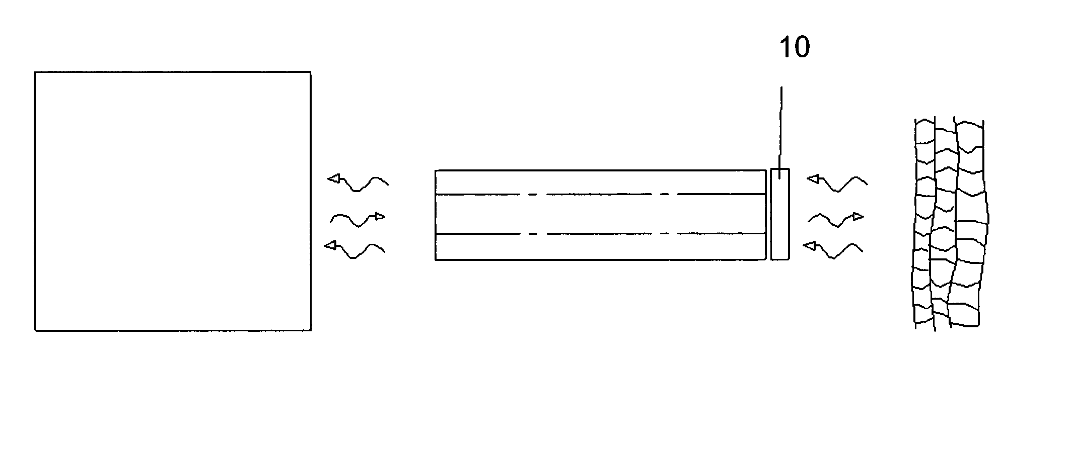
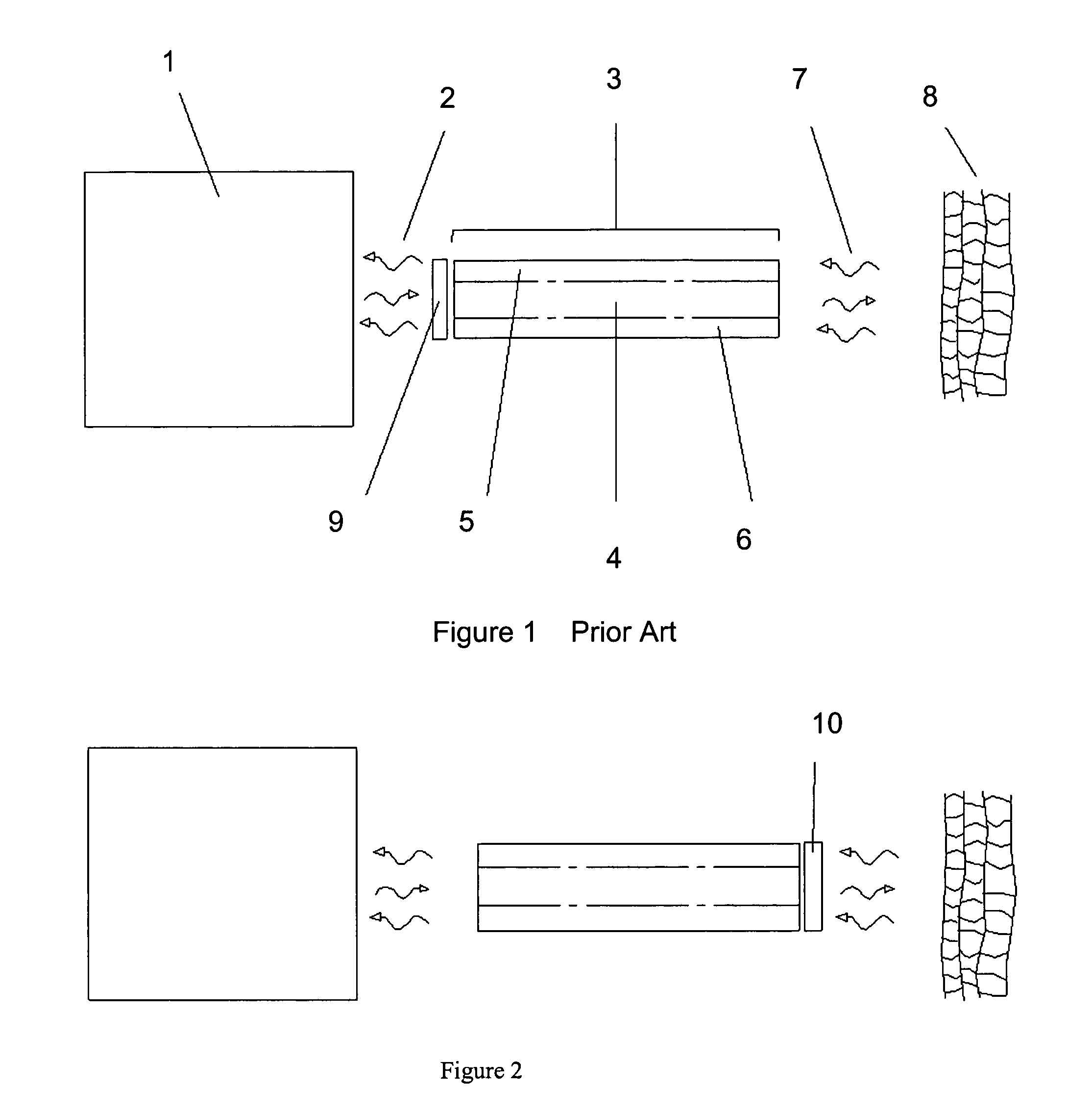
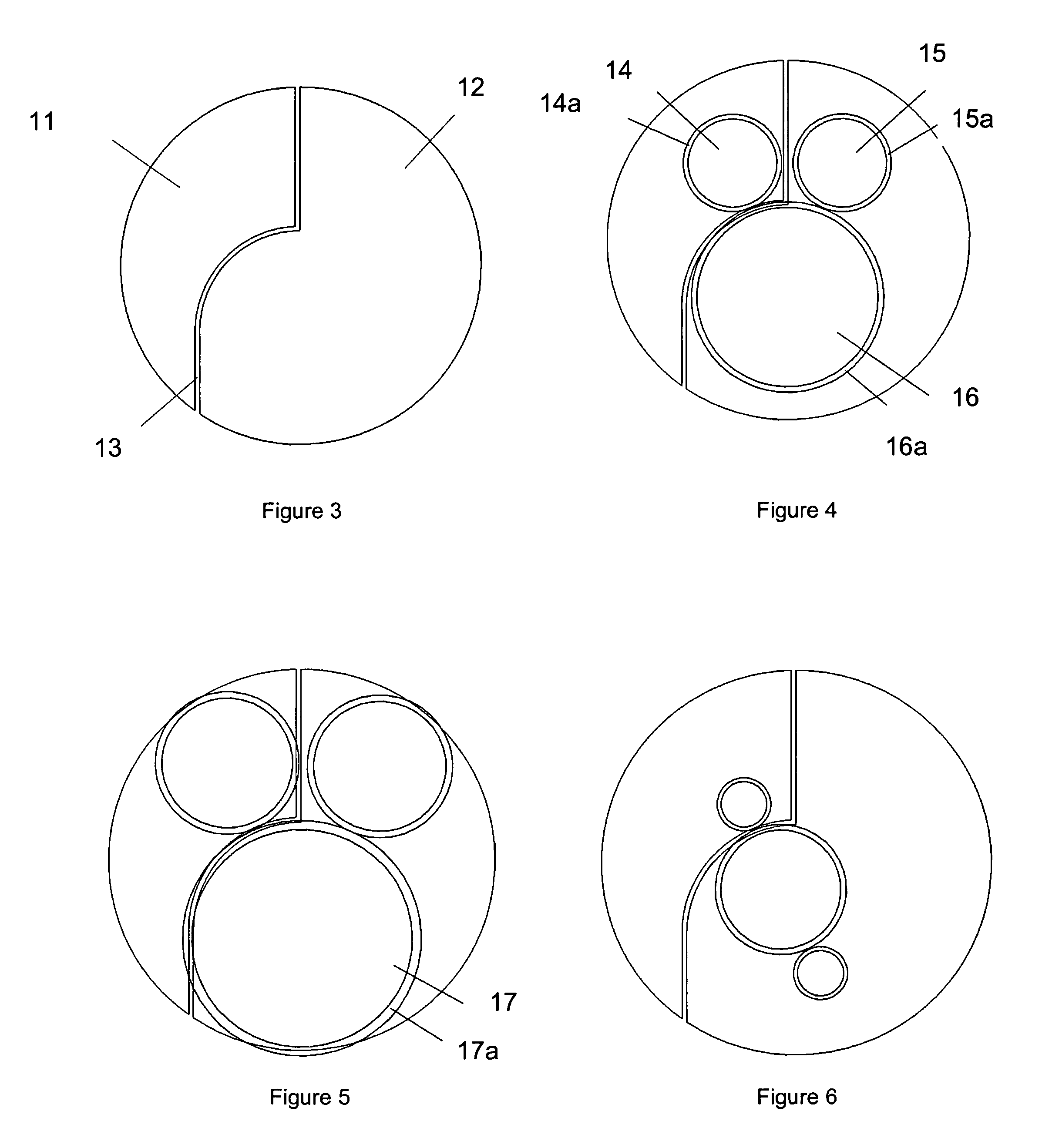
[0045]An embodiment of the present invention is shown schematically in FIG. 2. Pixelated variably-polarizing substrate assembly 10 is placed at the sample end of probe 3. Substrate assembly 10 has one or more discrete polarized areas defining particular polarization orientations, each such area (called a “pixel” herein) defining a single polarization axis. In most applications in which there are two pixels, the polarization axes of the pixels will be orthogonal with respect to one another. The pixels are sized, shaped and located to correspond to the size, shape and location at the probe sample end of the optical channels of the probe. Pixelated substrate assembly 10 has a thickness that results in an acceptable level of Fresnel reflections in small diameter probes (defined as probes with a distal tip diameter of less than 25 mm, and preferably less than about 10 mm). Typically, pixelated substrate assembly 10 is no more than about 200 microns thick.

[0046]This invention accomplishes...


PUM

PropertyMeasurementUnit
thickaaaaaaaaaa
grazing angle techniqueaaaaaaaaaa
depthaaaaaaaaaa

Abstract

A variably-polarizing optical probe assembly. The assembly includes an optical probe having one or more optical light delivery channels that emit incident light from the sample end of the probe toward a sample being investigated, and one or more optical light-receiving channels that receive incident light from the sample. A variably-polarizing substrate assembly is coupled to the sample end of the probe. The substrate assembly includes an optically transmitting substrate and one or more discrete polarizer areas on a face of the substrate, each such polarizer area defining a polarization orientation, with the polarizer areas together defining one or more different polarization orientations. The substrate assembly is arranged relative to the probe such that one polarizer area covers at least one light delivery channel and one polarizer area covers at least one light-receiving channel.

Description

GOVERNMENT RIGHTS[0001]This invention was made with Government support under (Grant Number 1 R43 CA103083-01) awarded by the National Institutes of Health (NIH). The Government has certain rights in the invention. The inventor is an employee of the assignee, Optimum Technologies, Inc. of Southbridge, Mass.FIELD OF THE INVENTION[0002]This invention relates to polarized optical probes.BACKGROUND OF THE INVENTIONMethods of Optical Analysis[0003]Photons from the ultraviolet, optical, and infrared portions of the electromagnetic spectrum have been used for over 100 years to investigate the properties of matter. These techniques, hereinafter referred to as “methods of optical analysis”, include but are not limited to Raman spectroscopy, infrared (IR) spectroscopy, atomic absorption spectroscopy, diffuse reflectance spectroscopy, fluorescence spectroscopy, photoluminescence spectroscopy, and elastic scattering spectroscopy.[0004]In Raman spectroscopy, a sample is irradiated with a substant...

Claims


Application Information

Patent Timeline
Patent Type & Authority Patents(United States)
IPC IPC(8): G01J4/00G01J4/04G01N21/21
CPCG01N21/21G01J4/04
Inventor CHINNOCK, RANDAL B.MELANSON, JEFFREY S.
Owner OPTIMUM TECH
Why Eureka
Try Eureka