Optical MEMS cavity having a wide scanning range for measuring a sensing interferometer

a sensing interferometer and optical mems technology, applied in the field of micro-electromechanical tunable fabryperot demodulators, can solve the problems of inability to reliably test the reliability of intensity-based sensors, gratings require expensive optical demodulators, and high-performance optical demodulators are still too expensive and bulky to compete with conventional electrical sensors. , to achieve the effect of low cost and low finess

Active Publication Date: 2007-03-06
OPSENS
View PDF18 Cites 81 Cited by
  • Summary
  • Abstract
  • Description
  • Claims
  • Application Information

AI Technical Summary

Benefits of technology

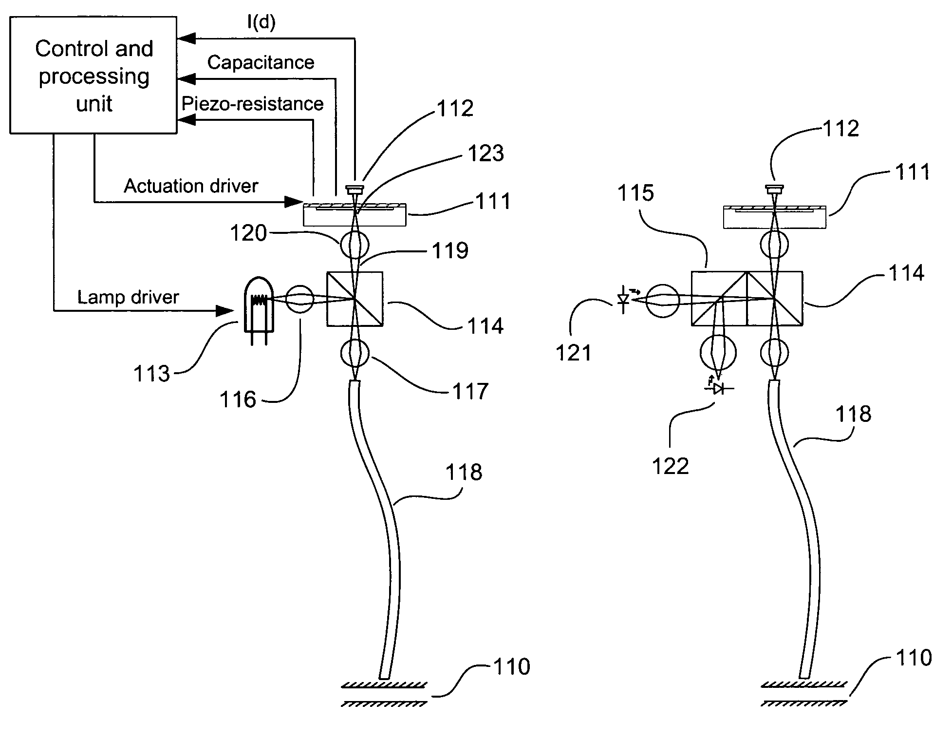
[0009]Accordingly, it is an object of the present invention is to provide a low cost microelectromechanical low finesse tuneable Fabry-Perot demodulator used as a local interferometric correlator for measuring the path length difference of a remote interferometric fiber optic sensor.
[0013]It is a further object of the invention to provide a low cost high performance optical demodulator for measuring the path length difference of single mode or multimode fiber optic interferometric sensors.
[0017]It is a second large aspect of the present invention to provide a method and a Fabry-Perot cavity MEMS device having a diaphragm that can be brought into oscillation to thereby vary the length of the Fabry-Perot cavity.
[0018]More specifically, it is provided a method for varying a cavity length of a micro-electromechanical system (MEMS) Fabry-Perot cavity. The method comprises providing a MEMS Fabry-Perot cavity formed by a first surface and a second surface, one of the surfaces forming at least a part of a deflectable diaphragm and bringing the diaphragm in oscillation at a diaphragm natural oscillation frequency to thereby vary the cavity length of the MEMS Fabry-Perot cavity.
[0021]More specifically, it is provided a method for varying a cavity length of a micro-electromechanical system (MEMS) cavity. The method comprises providing a MEMS cavity formed by a first surface and a second surface, the second surface forming at least a part of a deflectable diaphragm, wherein said deflectable diaphragm has a pre-determined shape and a perimeter. Finally, the method comprises deflecting the diaphragm towards the first surface, starting at the perimeter of the diaphragm, to thereby vary the cavity length of the MEMS cavity.

Problems solved by technology

Intensity based sensors never proved to be reliable, while fiber Bragg gratings require a costly optical demodulator for measuring minute wavelength shift.
High performance optical demodulators however are still too expensive and bulky too compete with conventional electrical sensors.
Laser light source are however limited to the measurement of the relative change of interferometric sensors and thus, they are limited to dynamic measurements as taught by U.S. Pat. No. 5,301,001 Murphy et al., Apr. 5, 1994.
Wavelength stability is however costly to achieve.
But unless the severity of the environment justifies it, these methods are nonetheless too expensive and bulky to compete with conventional techniques.
Another drawback comes from the use of low cost silicon CCD array detectors that limit the wavelength of the light source below 1000 nm, thus preventing the use of most telecommunication components in the near infrared, such as LED's and single mode fibers.
This method is however poorly efficient with a very low throughput that limits speed, resolution, accuracy and long term stability of the measurement.

Method used


Image

  • Optical MEMS cavity having a wide scanning range for measuring a sensing interferometer
  • Optical MEMS cavity having a wide scanning range for measuring a sensing interferometer
  • Optical MEMS cavity having a wide scanning range for measuring a sensing interferometer

Examples


first embodiment

of the Present Invention

[0068]FIG. 6 shows a first embodiment 70 of a micro-electromechanical (MEMS) Fabry-Perot demodulating interferometer (MEMS-FPDI) based on the use of silicon micromachining techniques. It comprises a low finesse FP interferometer with a first mirror 71 made by depositing a semi-reflective mirror on the inner surface of a glass substrate 73, and a second mirror 72 made of the inner surface of a silicon diaphragm 74. The second mirror 72 made of said inner surface of the silicon diaphragm can be scanned by applying a voltage between the two electrodes 75, 76, the first electrode 75 being made by depositing a first metal layer on the glass substrate, and the second electrode 76 being made by depositing a second metal layer on the silicon diaphragm. The distance between the two mirrors, and hence the FP cavity length 78, is monitored by measuring the capacitance between said electrodes 75, 76. A layer of SiO2 77 is deposited so as to fully cover the surface of the...

second embodiment

of the Present Invention

[0096]A second preferred embodiment 300 involves the use of four tethers 301 connecting the diaphragm 302 to the silicon substrate 303. FIG. 9 illustrates the internal view of such a diaphragm connected to the silicon substrate with tethers. The natural frequency of such an embodiment can be reduced to 1000 Hz and lower, while also reducing the voltage required to deflect the diaphragm. One method to construct this tether diaphragm is provided herein after.

[0097]A thin silicon diaphragm 303 25 μm thick is temporarily bonded on a glass substrate (handle). The surface of the silicon diaphragm is coated with chrome and with a photoresist. The photoresist and the chrome layers are patterned to etch through the silicon so that all four tethers 301, the center of the diaphragm 302 and the openings 310, 311 for the connecting pads 312, 313 are formed. The total diameter of the diaphragm and tethers is still 6 mm, but the center of the diaphragm 302 is reduced to 4 m...

third embodiment

of the Present Invention

[0099]A third preferred embodiment 80 for reducing the actuation voltage while reducing the size of the diaphragm is described herein after. The third preferred embodiment 80 for the construction of a FPDI is shown in FIG. 10, where the diaphragm 81 is pulled toward the glass cover 82 with a Ziploc-like motion. According to relation (4), the force becomes extremely high when the electrodes 87, 88 are in very close proximity. It is then desirable to bring the electrodes in closer proximity, or at least a portion of the same. The edge of the diaphragm 83 is initially in very close proximity with the glass substrate 84. By applying a voltage, a large electric field is created near the edge 83 of the diaphragm 81, where the separation between the electrodes 87, 88 is minimal. The resulting force is then very high, pulling the edge of the diaphragm 83 in close contact with the substrate. A larger force is subsequently induced toward the center of the diaphragm, as...


PUM


Abstract

A method for measuring the cavity length of a remote sensing interferometer by locally replicating the state of the remote sensing interferometer by way of a local interferometer. The local interferometer is produced by micro-electromechanical micro machining techniques, thus obtaining a highly accurate and reliable fiber optic sensing at a cost comparable to electronic sensing devices.

Description

CROSS-REFERENCE TO RELATED APPLICATIONS[0001]This is the first application for this invention.FIELD OF THE INVENTION[0002]The invention relates to micro electromechanical device systems (MEMS). More specifically, the invention relates to a microelectromechanical tunable Fabry-Perot demodulator.BACKGROUND OF THE INVENTION[0003]Fiber optic sensors are considered as valuable replacements to conventional sensors for environments where immunity against electromagnetic field, small size and high operating temperature are required. Numerous types of sensors have been developed over the years including, among others, intensity, interferometric and wavelength based sensors. Intensity based sensors never proved to be reliable, while fiber Bragg gratings require a costly optical demodulator for measuring minute wavelength shift. Fabry-Perot interferometric sensors deliver very good performance, they are flexible as they can be built to measure most physical and chemical parameters, and the sen...

Claims


Application Information

Patent Timeline
Patent Type & Authority Patents(United States)
IPC IPC(8): G01B11/02G01B9/02G02B26/00G01J3/02G01J3/26
CPCG01J3/02G01J3/0256G01J3/26G02B26/001G01B9/02007G01B9/02065G01B9/02023G01B9/02051G01B2290/25
Inventor BELLEVILLE, CLAUDE
Owner OPSENS
Why Eureka
Try Eureka