Electronic control unit

a control unit and electronic technology, applied in the direction of electrical apparatus casings/cabinets/drawers, electrical apparatus connection, casings/cabinets/drawers, etc., can solve the problems of large size, high cost, and complicated structure of conventional ecu ventilation structure, so as to reduce pressure difference, prevent contaminants, and simple structure

Inactive Publication Date: 2007-03-13
NSK LTD +1
View PDF11 Cites 32 Cited by
  • Summary
  • Abstract
  • Description
  • Claims
  • Application Information

AI Technical Summary

Benefits of technology

[0023]The present invention has been achieved under these circumstances, and an object of the present invention is to provide an ECU which can prevent clogging of a ventilation hole and a filter to improve ventilation efficiency, and which is simple in structure and lower in cost.
[0024]The object of the present invention is attained by providing an ECU which has a ventilation section so as to reduce the difference in temperature and pressure between the interior and the exterior of the ECU-case, and the ventilation section is simple in structure and low-cost. That is,
[0030]Still Furthermore, the above object is more effectively attained by that the ECU comprises a ventilation hole which communicates the interior and the exterior of the ECU-case with each other, so as to reduce the pressure difference between the interior and the exterior of the ECU-case resulting from an increase of temperature or pressure within the ECU-case due to a self-heating element.
[0032]According to the ECU of the present invention, the ventilation hole which communicates the interior and the exterior of the ECU-case with each other is provided in the ECU-case, the filter is arranged in the ventilation hole formed in the ventilation section, and the sectional area of the ventilation hole is gradually enlarged toward the interior of the ECU-case, with an inlet of the ventilation hole narrowed. As a result, according to the present invention, a ventilation mechanism of the ECU can be realized by a simple structure. In addition, even if the ECU is disposed in an environment in which water relatively frequently splashes on the ECU such as in an engine room, and the temperature or the pressure within the ECU-case rises due to a self-heating element within the ECU, then it is possible to reduce the pressure difference between the interior and the exterior of the ECU-case, and prevent the contaminants such as water, dust, and the like from entering into the ECU-case.
[0033]Further, since the inlet of the ventilation hole is narrowed, it is possible to prevent contaminants such as water or dust from being directly hit against the filter from the outside. Even if such contaminants as water, salt water, or muddy water enter into the ventilation hole, an impact speed at which the contaminants is hit against the filter can be decreased and the filter can be prevented from being damaged, by gradually enlarging the sectional area of the ventilation hole toward the interior of the ECU-case. Besides, it is possible to prevent clogging of the filter caused by adhesion of the water, salt water, muddy water, or the like onto the filter, and prevent deterioration of filter function. Consequently, it is made difficult to damage the filter, thus improving durability of the filter.

Problems solved by technology

As above described, the ventilation structure of the conventional ECU has a drawback that it is complicated in structure, large in size, and costs too much.

Method used


Image

  • Electronic control unit
  • Electronic control unit
  • Electronic control unit

Examples


first embodiment

(First Embodiment)

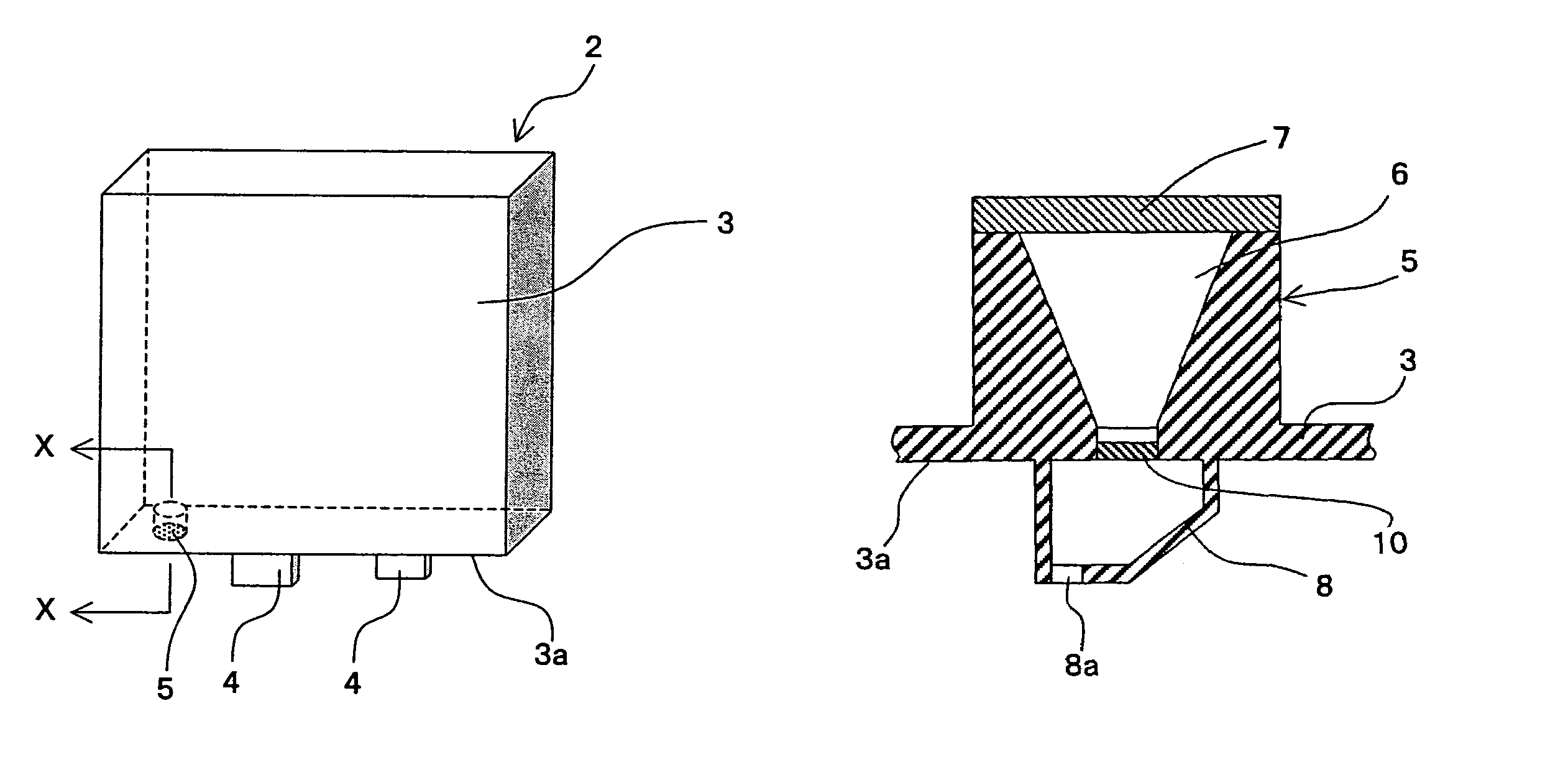
[0056]FIG. 4 is a perspective view which depicts a front structure of an automobile. In an engine room A, an ECU 2 is attached to a partition 1 of the engine room A from a cabin. As enlarged and shown in FIG. 5 in detail, this ECU 2 is constituted so that connectors 4, 4 are provided on a bottom of ECU-case 3a of an ECU-case 3 which stores electronic components such as a power transistor serving as a heating element and a microcomputer, and so that the connectors 4, 4 are connected with various sensors such as a torque sensor through a harness.

[0057]A ventilation section (breathing section) 5 which communicates an interior and an exterior of the ECU-case 3 with each other is provided on the bottom of ECU-case 3. The ventilation section 5 reduces a pressure difference between the interior and the exterior of the ECU-case 3 resulting from a rapid increase of temperature or pressure of the air within the ECU-case 3. As shown in FIG. 6, this ventilation section 5 is fo...

second embodiment

(Second Embodiment)

[0064]FIG. 7 depicts a second embodiment of the present invention. A ventilation section 5 is equal in structure to that according to the first embodiment. The ventilation section 5 comprises a tapered ventilation hole 6 so that a sectional area of the hole 6 is gradually enlarged toward an interior of an ECU-case 3, and a filter 7 is attached to the interior of the ventilation hole 6 so as to prevent entry of water, dust, or the like.

[0065]According to this second embodiment, a barrier room 8 is provided on the ECU-case 3 so as to cover an inlet of the ventilation hole 6, and a small hole 8a is formed in a part of the barrier room 8. As a result, even if water, dust, or the like enter into the ECU-case 3 from the outside, the contaminants stay within the barrier room 8. Therefore, it is possible to prevent the contaminants from directly entering into the ventilation hole 6, and decrease an entry speed of the contaminants. Hence, the second embodiment can exhibit ...

third embodiment

(Third Embodiment)

[0066]FIG. 8a depicts a third embodiment of the present invention. A ventilation section 5 is equal in structure to that according to the second embodiment. The ventilation section 5 comprises a tapered ventilation hole 6 so that a sectional area of the ventilation hole 6 is enlarged toward an interior of an ECU-case 3. In addition, a filter 7 is attached to the interior of the ventilation hole 6, a barrier room 8 is provided on the exterior of the ventilation hole 6 so as to cover an inlet of the ventilation hole 6, and a small hole 8a is formed in a part of the barrier room 8.

[0067]According to the third embodiment, a circular small hole is formed at the exterior of the ventilation hole 6, and a barrier net 10 composed of an annular member 10a fitted and inserted into the small hole and a shield rod 10b radially extending from a center of the small hole is arranged on the exterior of the ventilation hole 6. It is thereby possible to prevent the contaminants such ...


PUM


Abstract

An Electronic Control Unit which houses electronic circuit for controlling various devices of vehicles in a sealing case is characterized in that the case has a ventilation hole to communicate an interior and an exterior of the case, the ventilation hole comprises a filter for preventing from entering contaminants from the outside, and a sectional area of the ventilation hole is gradually enlarged toward the interior of the case.

Description

FIELD OF THE INVENTION[0001]The present invention relates to an Electronic Control Unit (hereinafter referred to as the “ECU”), and more particularly to an improved ECU which is installed in an engine room et al.BACKGROUND OF THE INVENTION[0002]Generally, the ECU for controlling the driving of various devices such as an electric motor is mounted not only in the interior, but also in the exterior of a car. This ECU is constructed by a case (hereinafter referred to as the “ECU-case”) for housing an electronic circuit (hereinafter referred to as the “ECU-circuit”) constituted by electronic parts such as CPU. The ECU-case consists of an ECU-case body, ECU-case lid covering over the ECU-case body. Harnesses for transmitting various input or output signals, cables leading to power source, and grounded wires are connected to the ECU-circuit.[0003]The ECU has a ventilation hole (a vent) in the ECU-case to regulate the pressure within the ECU-case so as to avoid an adverse effect by thermal ...

Claims


Application Information

Patent Timeline
Patent Type & Authority Patents(United States)
IPC IPC(8): H05K5/00F02D1/00B60R16/02B60R16/023B62D5/04H05K5/02H05K7/20
CPCB60R16/0239H05K5/0215H05K5/0213
Inventor SAKATA, TAKESHI
Owner NSK LTD
Why Eureka
Try Eureka